
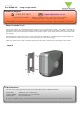
User Manual

Fitting
1
2
3
4
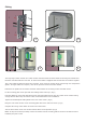
Determine the position of the reader and mark and drill holes for the xing screws and cable access.
Fix the mounting plate to the post with the locating hooks at the top. (Fig 1)
Feed the cables for power and data thorough the mounting plate and into the rear section of the reader leaving
enough slack to allow easy connection to the circuit boards later in the installation.
Tighten the weatherproof cable glands at the rear of the reader. (Fig 2)
Hang the rear reader section on the mounting plate and secure with two screws. (Fig 3)
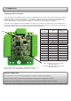
Complete the wiring of the reader as shown in this instruction.
Join the front section to the rear section with the Allen screws provided. (Fig 4)
NOTE: It may be necessary to briey remove the reader from its mounting plate if access to the Allen screws is
limited by the post or wall.
The long range reader consists of a reader module mounted inside the front half of the housing and a hands free
interface mounted inside the rear half. An interconnect cable is supplied that connects the two sections together.
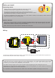
Two 5 yard cables for data and power are provided. These enter the module at the rear through two compression
glands. If longer cables are required, refer to the previous section for further details.
1
2
3
4