
User Manual

12v
Red LED
Amber LED
Green LED
Data/D0
Net2
Control Unit
Clock/D1
Media Detect
0V
Entry
12v
Red LED
Amber LED
Green LED
Data/D0
Clock/D1
Media Detect
0V
Entry
Green LED
Exit/Entry
0V
12V
Net2Air Interface
Reader
Red 12v dc
Brown
Keypad 2 Reader 2
Orange
Green
Yellow
Blue
Mauve
Black/White
Brown
Yellow
Orange
+12V
0V
N.C.-
N.O.-
Com
N.C.-
N.O.-
Com
Alarm Output
0V
Contact
0V
Exit
0V
Tamper
PSU
RX
TX
Relay 1
Relay 2
Exit
Contact
Tamper
PSU
OK
5V
12V
Red
Brown
Orange
Green
Yellow
Blue
Mauve
Black/White
Brown
Yellow
Orange
Networkj
CAT5 Cable coding
White/Green
Green
White/Orange
Orange
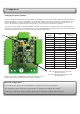
1
2
3
4
Screen or spare cores
from network cable
Seriel number
241821
TestID: 012345678901
z-14401
3
2 4 89 8 0 0 00 0
4
PowerRelay 1Relay 2
Inputs
12Vdc
Power Supply
Not Connected
Not Conne
cted
Not Conne
cted
Reader 1
Keypad1
Caution: For 12V d.c readers only. For
connection of old 5v readers, refer to
instructions
12v
Red LED
Amber LED
Green LED
Data/D0
Net2
Control Unit
Clock/D1
Media Detect
0V
Entry
12v
Red LED
Amber LED
Green LED
Data/D0
Clock/D1
Media Detect
0V
Entry
Green LED
Exit/Entry
0V
12V
Net2Air Interface
Reader
Red 12v dc
Brown
Keypad 2 Reader 2
Orange
Green
Yellow
Blue
Mauve
Black/White
Brown
Yellow
Orange
+12V
0V
N.C.-
N.O.-
Com
N.C.-
N.O.-
Com
Alarm Output
0V
Contact
0V
Exit
0V
Tamper
PSU
RX
TX
Relay 1
Relay 2
Exit
Contact
Tamper
PSU
OK
5V
12V
Red
Brown
Orange
Green
Yellow
Blue
Mauve
Black/White
Brown
Yellow
Orange
Networkj
CAT5 Cable coding
White/Green
Green
White/Orange
Orange
1
2
3
4
Screen or spare cores
from network cable
Seriel number
241821
TestID: 012345678901
z-14401
3
2 4 89 8 0 0 00 0
4
PowerRelay 1Relay 2
Inputs
12Vdc
Power Supply
Not Connected
Not Conne
cted
Not Conne
cted
Reader 1
Keypad1
Caution: For 12V d.c readers only. For
connection of old 5v readers, refer to
instructions
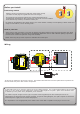
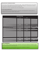
Wiring
It is important to run an appropriate power cable to the reader that is capable of carrying a current of 1A.
A data cable must be run from the control unit to the reader interface. The recommended cable for this is Belden
9540; a 10 core overall screened cable with a maximum cable length of 100 yards. Spare cores should be used
to double up on the power wires (Red/Black) to the interface.
The reader requires a higher current (up to 1A) than can be supplied by the ACU reader port and so an
independent 12V DC power feed must be provided. As per the wiring diagram, the spare outputs on the Paxton
2A boxed power supply can be used for this purpose.
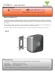
Before you install
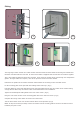
Read in, read out
When using in and out readers, users may be picked up by both readers as they move through the door which
will effect the reliability of any Roll Call or Antipassback application. Ensure that sufcient spacing is provided
between these readers for optimum range and reliability.
Positioning readers
For maximum read range the Hands Free reader eld should not be
overlapped by the eld from other interference sources at or around 125KHz.
These include Loop readers, non Paxton readers, etc.
Readers should not positioned so that their active elds overlap.
(see table on back page for typical hand free read ranges)
For optimum keyfob battery life please choose your reader location carefully to avoid placing it within hands free
range of work stations, rest or smoking areas.
NOTE: Each long range reader requires a dedicated ACU reader port.
To achieve the maximum range for the device, the interface PCB has been mounted upside down to position the
internal aerial away from other reader components.