
Phau Ntawv Qhia

Page 1
www.sensata.com
Copyright © 2022 Sensata Technologies, Inc.
|DHX5 IO-LINK OPERATING INSTRUCTIONS
– FIRMWARE V1.2
INSTALLATION GUIDE
ELECTRICAL INSTALLATION
Pin
number
Function -
Incremental mode
Function - IO-link
mode
Illustration
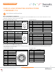
1 V+ L+: power supply
2 A incremental signal N.C.
3 GND L-: power supply
4 Z incremental signal IO-Link
5 B incremental signal N.C.
Color Function - Incremental mode Function - IO-link mode
White GND L-: power supply
Blue V+ L+: power supply
Grey A incremental signal N.C.
Brown B incremental signal N.C.
Red Z incremental signal IO-Link
Pink A/ incremental signal N.C.
Green B/ incremental signal N.C.
Black Z/ incremental signal N.C.
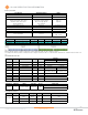
Color Function - Incremental mode Function - IO-link mode
White GND L-: power supply
Brown V+ L+: power supply
Green A incremental signal N.C.
Yellow B incremental signal N.C.
Grey Z incremental signal IO-Link
Pink A/ incremental signal N.C.
Blue B/ incremental signal N.C.
Red Z/ incremental signal N.C.
Color Description
White L- power supply GND
Blue L+ power supply V+
Grey A incremental signal
Brown B incremental signal
Red Z incremental signal
Pink A/ incremental signal
Green B/ incremental signal
Black Z/ incremental signal
Brown / Grey IO-Link
Pin
number
Function -
Incremental mode
Function - IO-link
mode
Illustration
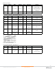
1 GND L-: power supply
2 V+ L+: power supply
3 A incremental signal N.C.
4 B incremental signal N.C.
5 Z incremental signal IO-Link
6 A/ incremental signal N.C.
7 B/ incremental signal N.C.
8 Z/ incremental signal N.C.
Pin number Description Illustration
1 L- power supply GND
2 L+ power supply V+
3 A incremental signal
4 B incremental signal
5 Z incremental signal
6 A/ incremental signal
7 B/ incremental signal
8 Z/ incremental signal
9 IO-Link
10 N.C.
11 N.C.
12 N.C.
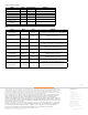
RGY : Incremental OR IO-link on Z (multiplexed)
There are two different modes, by default the encoder is in incremental mode. After an IO-link WAKEUP request, the encoder switches in IO-Link mode : the Z incre-
mental signal is disabled and is configured to be the IO-link C/Q pin.
Electronics RGZ : Incremental AND IO-link (simultaneous)
For this configuration, the incremental signals and IO-link are all available simultaneously. Then the incremental signals can be incoherent few milliseconds after a
configuration update from an IO-link command.
BF : Connector M12 5 pins (Device class B) GP : PUR cable 8 wires
G3 : PVC cable 8 wires
IP : PUR cable 9 wires
GM : Connector M12 8 pins
I6 : Connector M23 12 pins CW
*Adapter M12 8 pins to M12 5 pins (IO-link device class B) reference : to define
* Adapter M23 12 pins to M12 5 pins (IO-link device class B) reference : to define