
Installation Guide

Page 1
www.sensata.com
Copyright © 2022 Sensata Technologies, Inc.
|AHX5 IO-LINK OPERATING INSTRUCTIONS
– FIRMWARE V1.1
INSTALLATION GUIDE
ELECTRICAL INSTALLATION
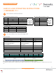
Pin number Function - Incremental mode Function - IO-link mode Illustration
1 Brown L+ : power supply V+
2 White N.C.
3 Blue L- : power supply GND
4 Black IO-Link
5 Grey N.C.
Pin number Description Illustration
1 L+ : power supply V+
2 N.C.
3 L- : power supply gnd
4 IO-Link
5 N.C.
Pin number Color Description
1 Brown L+ : power supply V+
2 White L- : power supply GND
3 Green IO-Link
BD : PUR Cable M12 5 pins (Device class B)
BF : Connector M12 5 pins (Device class B)
BJ : PVC Cable 3 wires
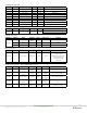
IO-LINK SPECIFICATION INFORMATION
Specification IO-Link description Value
Transfer rate COM3 230.4 kBaud
Minimum cycle time of device Minimum cycle time 0x0A (1ms)
Frame specification
Amount of preoperate data required
Amount of operate data required
Enhanced parameters
M-Sequence Capability:
M-Sequence Type Preoperate
M-Sequence Type Operate
ISDU supported
TYPE_0
TYPE_2_V
Supported
IO-Link protocol version Revision ID 0x11 (Version 1.1)
Amount of process data from the device to the master ProcessDataIn 0x83 (4 bytes)
Amount of process data from the master to the device ProcessDataOut 0x00 (0 byte)
Manufacturer ID Vendor ID 0x0468 (1128)
Device identification Device ID 0x0004
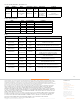
Device specification
Name Description Datatype Bitoffset Bitlength Value Range Unit
Speed Rotating speed IntegerT 15 16 -12000 to 12000 rpm
Position Absolute position counter UIntegerT 0 16 0 to 65535
Process data
When the absolute position resolution is configured to a value smaller than 16 bits, the data is aligned on the bit 0.
For example, if the absolute position resolution (index 90) is configured to 12 bits, the bits 0 to 11 will contain the data. Bits 12 to 15 will then be unused and set to
zero.