
- Patton Electronics Network Hardware User Manual


Sync Serial port 63
SmartNode 4900 User Manual C • Port pin-outs
Sync Serial port
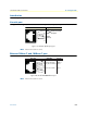
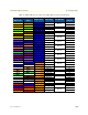
Two types of serial ports are available: V.35 or X.21. They are configured as DTE. The V.35 is presented on a
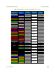
DB-25 female connector (see table 14 for pin-outs). The X.21 is presented on a DB-15 female connector (see
table 15 for pin-outs).
Note
Pins not listed are not used
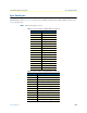
Table 14. V.35 serial port signals (DB-25 connector)
Pin Description
1 Frame Ground
2 TD-a (to DCE)
3 RD-a (from DCE)
4 RTS (to DCE)
5 CTS (from DCE)
6 DSR (from DCE)
7 Signal Ground
8 CD (from DCE)
9 RC-b (from DCE)
11 XTC-b (to DCE)
12 TC-b (from DCE)
14 TD-b (to DCE)
15 TC-a (from DCE)
16 RD-b (from DCE_
17 RC-a (from DCE)
20 DTR (to DCE)
24 XTC-a (to DCE)
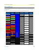
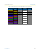
Table 15. X.21 serial port signals (DB-15 connector)
Pin Description
1 Signal Ground
8 DTE Common Return
2 Transmit (to DCE)
3 Control (to DCE)
4 Receive (from DCE)
5 Indication (from DCE)
6 Signal Element Timing (from DCE)
9 Transmit (to DCE)
10. Control (to DCE)
11 Receive (from DCE)
12 Indication (from DCE)
13 Signal Element Timing (from DCE)