
- Patton Electronics Network Hardware User Manual

Installing the IpChannel Bank 32
SmartNode 4900 User Manual 3 • Hardware installation
Note
Some NTUs have non-standard connections and require special
cables. Consult the NTU maker’s product documentation
Connecting power
In connecting to the power source, it is important to establish a good grounding connection first, then the
power connection. This section explains:
• Making the ground connection for either AC or DC units (see section “Grounding the Model SN4900—
AC and DC units”)
• Connecting to an AC power source (see “Installing the power cables—AC units” on page 33)
• Connecting to a DC power source (see “Installing the power cables—DC units” on page 34)
Grounding the Model SN4900—AC and DC units
Do the following:
1. Assemble a ground wire using #10 AWG wire with green-colored insulation and two ring terminals. Make
the wire long enough to reach one of the following earth ground sources:
– The building ground rod (generally located at the site’s main service entrance)
– A sprinkler system pipe
– A cold-water pipe
– Building structural steel
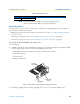
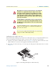
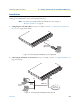
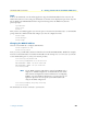
Figure 11. IEC-320 connector and grounding stud locations
2. Install the grounding wire between the grounding stud (see figure 11) and the grounding source.
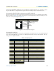
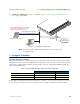
24 XTC-a (to DCE)
Table 8. Serial port pin-outs
V.35 Interface (DB-25) X.21 interface (DB-15)
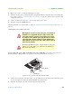
Power cable
retainer clip
Grounding stud
IEC-320 connector
(2 places)