
- Patton Electronics Network Hardware User Manual

Installing the IpChannel Bank 31
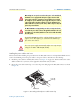
SmartNode 4900 User Manual 3 • Hardware installation
Connecting a 10/100Base-T Ethernet port to an Ethernet-capable workstation. The 10/100Base-T Ether-
net ports can connect to a single Ethernet-capable workstation or PC by means of any Ethernet cable.
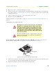
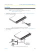
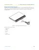
Connecting the EIA-561 RS-232 configuration port (DCE configured)
Install the supplied RJ-45-to-RJ-45 cable with the DB9-RJ45 adapter between the SN4900 IpChannel Bank
RS-232 console port (figure 10) and an open serial port on your computer. If you need to assemble your own
cable, refer to the pinout diagram in figure 10.
Figure 10. DB-9-to-RJ-45 cable diagram
Connecting the serial port
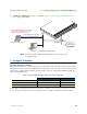
Serial devices (V.35 or X.21) are connected to the SmartNode’s serial ports (see table 8) via a cable terminated
at the SmartNode 4900. The V.35 connector is a DB-25 female and the X.21 uses a DB-15 female. The sync
serial ports are configured as DTE.
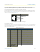
Table 8. Serial port pin-outs
V.35 Interface (DB-25) X.21 interface (DB-15)
Pin Description Pin Description
1 Frame Ground 1 Signal Ground
2 TD-a (to DCE) 2 Transmit (to DCE)
3 RD-a (from DCE) 3 Control (to DCE)
4 RTS (to DCE) 4 Receive (from DCE)
5 CTS (from DCE) 5 Indication (from DCE)
6 DSR (from DCE) 6 Signal Element Timing (from DCE)
7 Signal Ground 8 DTE Common Return
8 CD (from DCE) 9 Transmit (to DCE)
9 RC-b (from DCE) 10 Control (to DCE)
11 XTC-b (to DCE) 11 Receive (from DCE)
12 TC-b (from DCE) 12 Indication (from DCE)
14 TD-b (to DCE) 13 Signal Element Timing (from DCE)
15 TC-a (from DCE)
16 RD-b (from DCE)
17 RC-a (from DCE)
20 DTR (to DCE)
6 DSR
1 CD
4 DTR
5 SG
2 RD (driven)
3 TD (received)
8 CTS
7 RTS
1
2
3
4
5
6
7
8
DSR & DTR are internally
wired together
RJ-45 Jack Signal NameDB-9