
- Patton Electronics Network Hardware User Manual


Planning the installation 27
SmartNode 4900 User Manual 3 • Hardware installation
Network information
When planning your installation there are certain critical considerations for the network connections. The fol-
lowing sections describe such considerations for several types of network interfaces.
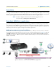
Network diagram
Draw a network overview diagram that displays all neighboring IP nodes, connected elements and
telephony components.
IP related information
Before you can set up the basic IP connectivity for your SmartNode 4900 series you should have the following
information (see table 7):
• IP addresses used for Ethernet LAN and WAN ports
• Subnet mask used for Ethernet LAN and WAN ports
• IP addresses used for the V.35 or X.21 serial WAN port
• Subnet mask used for the V.35 or X.21 serial WAN port
• IP addresses of central H.323 Gatekeeper (if used)
• IP addresses of central PSTN Gateway for H.323 based calls
• IP addresses of central TFTP Server used for configuration upload and download
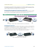
Configuration tools
You will need a PC (or equivalent) with a VT-100 emulation program (e.g. HyperTerminal) to configure the
software on your SmartNode 4900.
AC Power Mains
If you suspect that your AC power is not reliable, for example if room lights flicker often or there is machinery
with large motors nearby, have a qualified professional test the power. Install a power conditioner if necessary.
Refer to “Connecting power” on page 32.
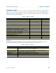
Table 7. IP addresses/subnets for SN4900
Port/Device IP Address IP Subnet
Ethernet LAN (ETH 0/1)
Ethernet WAN (ETH 0/0)
V.35 Serial port
X.21 Serial port
H.323 Gatekeeper (if used)
IP address of central PSTN gateway (H.323-based calls)
IP address of central TFTP server for configuration upload/downloads
The mains outlet that is utilized to power the equipment must be within
1 foot (3 meters) of the device and shall be easily accessible.
WARNING