Model 6081RC EdgeRoute Network Access Server User Manual Sales Office: +1 (301) 975-1000 Technical Support: +1 (301) 975-1007 E-mail: support@patton.com WWW: www.patton.com Part Number: 07MD6081RC-GS, Rev.
Patton Electronics Company, Inc. 7622 Rickenbacker Drive Gaithersburg, MD 20879 USA Tel: +1 (301) 975-1000 Fax: +1 (301) 869-9293 Support: +1 (301) 975-1007 Web: www.patton.com E-mail: support@patton.com Copyright © 2012, Patton Electronics Company. All rights reserved. The information in this document is subject to change without notice. Patton Electronics assumes no liability for errors that may appear in this document.
Summary Table of Contents 1 Model 6081RC overview ............................................................................................................................... 12 2 Hardware installation.................................................................................................................................... 20 3 Initial configuration ......................................................................................................................................
Table of Contents Summary Table of Contents ........................................................................................................................... 3 Table of Contents ........................................................................................................................................... 4 List of Figures ................................................................................................................................................. 7 List of Tables ..
Model 6081RC Network Access Server User Manual 3 Initial configuration ...................................................................................................................................... 28 Introduction ..........................................................................................................................................................29 1. Connecting the 6081RC to your PC ................................................................................................
Model 6081RC Network Access Server User Manual Console .................................................................................................................................................................42 Ethernet ................................................................................................................................................................43 D Port pin-outs ........................................................................................................
List of Figures 1 2 3 4 5 6 7 8 9 10 11 12 13 14 15 16 Model 6081RC EdgeRoute Network Access Router . . . . . . . . . . . . . . . . . . . . . . . . . . . . . . . . . . . . . . . . . . . . . 13 Model 6081RC front panel . . . . . . . . . . . . . . . . . . . . . . . . . . . . . . . . . . . . . . . . . . . . . . . . . . . . . . . . . . . . . . . 16 Model 6081RC Ethernet port LEDs . . . . . . . . . . . . . . . . . . . . . . . . . . . . . . . . . . . . . . . . . . . . . . . . . . . . . . . . .
List of Tables 1 2 3 4 5 6 General conventions . . . . . . . . . . . . . . . . . . . . . . . . . . . . . . . . . . . . . . . . . . . . . . . . . . . . . . . . . . . . . . . . . . . . . 10 Mouse conventions . . . . . . . . . . . . . . . . . . . . . . . . . . . . . . . . . . . . . . . . . . . . . . . . . . . . . . . . . . . . . . . . . . . . . . 11 LED definitions . . . . . . . . . . . . . . . . . . . . . . . . . . . . . . . . . . . . . . . . . . . . . . . . . . . . . . . . . . . . . . . . . . . . . . . .
About this guide This guide describes installing and configuring a Patton Electronics Model 6081RC EdgeRoute Network Access Router. By the time you are finished with this guide, your Network Access Router will be ready to accept routing or bridgin configurations. The instructions in this guide are based on the following assumptions: • The Model 6081RC will be installed in a Patton ForeFront chassis • There is a LAN connected to the Ethernet port of the Network Access Router • There are function cards (i.e.
Model 6081RC Network Access Server User Manual Precautions Notes and cautions, which have the following meanings, are used throughout this guide to help you become aware of potential Model 6081RC problems. Warnings relate to personal injury issues, and Cautions refer to potential property damage. Note Calls attention to important information. WARNING The shock hazard symbol and WARNING heading indicate a potential electric shock hazard.
Model 6081RC Network Access Server User Manual Table 1. General conventions Convention Meaning <> Angle brackets indicate function and keyboard keys, such as , , , and so on. Are you ready? All system messages and prompts appear in the Courier font as the system would display them. % dir *.* Bold Courier font indicates where the operator must type a response or command Mouse conventions The following conventions are used when describing mouse actions: Table 2.
Chapter 1 Model 6081RC overview Chapter contents Introduction ..........................................................................................................................................................13 Product overview ...................................................................................................................................................13 Hardware overview ..........................................................................................................
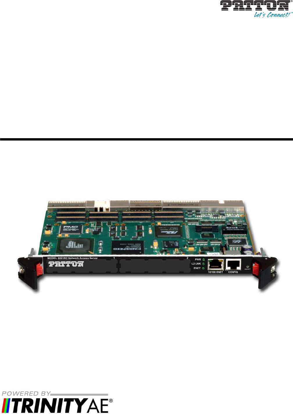
Model 6081RC Network Access Server User Manual 1 • Model 6081RC overview Introduction The Model 6081RC Network Access Router (see figure 1) is a MIPS-based processor blade for the ForeFront Access Infrastructure System (AIS). With hardware and software features optimized for Layer-2/Layer-3 networking, the 6081RC enables the AIS to deliver IP as an access infrastructure element as well as support the delivery of advanced broadband IP services and applications. Figure 1.
Model 6081RC Network Access Server User Manual 1 • Model 6081RC overview Network connections may come from any number of ForeFront interfaces. The 6018RC allows any resource card within ForeFront to deliver TDM and IP/packet services on a DS0-by-DS0, connection-by-connection basis.
Model 6081RC Network Access Server User Manual 1 • Model 6081RC overview The 6081RC’s applications give life to the hardware features of the 6081RC. Details of the software applications are indicated in the section 6081RC IP Access Server Functionality.
Model 6081RC Network Access Server User Manual 1 • Model 6081RC overview Handle MODEL 6081RC Network Access Server Mezzanine Card Interface 1 1 Mezzanine Card Interface 2 PWR LED 2 L2 LINK LED PWR ENET L2 LINK 10/100 ENET ENET LED 10/100 ENET port CONFIG port CONFIG READY READY LED Handle Figure 2.
Model 6081RC Network Access Server User Manual 1 • Model 6081RC overview LAN Ethernet port Front panel 10/100-Mbps Ethernet LAN port labeled ENET (ETH0) is presented on a RJ-45 connector with an auto-sensing/full-duplex 10Base-T or 100Base-T interface.
Model 6081RC Network Access Server User Manual 1 • Model 6081RC overview • Two LEDs per port (see figure 3): link/traffic LED (solid green when link is established; flashing green when the port has traffic) and 10/100 Mbps LED (solid yellow at 100 Mbps; off at 10 Mbps) Note When the Fast-Ethernet PMC module (part number PEC1/FENET/2/TX) is installed in PMC slot 2, you may redirect one or both internal Ethernet ports B and C to the front-panel RJ-45 connectors B and C.
Model 6081RC Network Access Server User Manual 1 • Model 6081RC overview • SYSLOG client • Remote software upgrade via FTP • Built-in HTTP server for complete configuration and control using a standard WWW browser PWR LED 2 L2 LINK LED PWR ENET L2 LINK 10/100 ENET ENET LED Link/Traffic LED CONFIG 10/100 Mbps LED READY READY LED Figure 4.
Chapter 2 Hardware installation Chapter contents Introduction ..........................................................................................................................................................21 Unpacking the Model 6081RC .............................................................................................................................21 Installing the PMC Ethernet Access Module onto the 6081RC front blade ...........................................................
Model 6081RC Network Access Server User Manual 2 • Hardware installation Introduction This chapter contains the following procedures for installing the Model 6081RC: • “Unpacking the Model 6081RC”—lists the contents in the 6081RC shipping container • “Model 6081RC blades installation”—describes installing the Network Access Router in a ForeFront chassis • “Cable installation” on page 25—describes installing network interface and terminal cables • “Completing the hardware installation” on page 27—describes
Model 6081RC Network Access Server User Manual 2 • Hardware installation Installing the PMC Ethernet Access Module onto the 6081RC front blade You may purchase an optional PMC Ethernet Access Module for the Model 6081RC. The PMC Ethernet Access Module may be factory installed, or you may order it separately for installation in the field. The Model 6081RC has two PMC expansion slots, numbered 1 and 2 (see figure 5).
Model 6081RC Network Access Server User Manual 2 • Hardware installation To install the Ethernet Access Module in your Model 6081RC, do the following: You must wear the anti-static strap to avoid electrostatic damage to the 6081RC or to the PMC Ethernet Access Module. CAUTION The 6081RC must not be installed in the chassis when installing the PMC Ethernet Access Module. CAUTION The PMC Ethernet Access Module must be installed in PMC slot 2. Do not install it in PMC slot 1. CAUTION 1.
Model 6081RC Network Access Server User Manual 2 • Hardware installation • The building ground rod (generally located at the site’s main ser- vice entrance) • A sprinkler system pipe • A cold-water pipe • Building structural steel 1. If you have not done so already, remove the Model 6081RC from its shipping container. Note Be sure to wear the anti-static strap to prevent electrostatic damage to the blade. Note The location should be well ventilated. Do not block the rack chassis’ cooling vents. 2.
Model 6081RC Network Access Server User Manual 2 • Hardware installation Cable installation This section describes installing the network interface cables. CAUTION The interconnecting cables shall be acceptable for external use and shall be rated for the proper application with respect to voltage, current, anticipated temperature, flammability, and mechanical serviceability. Connecting the Ethernet ports The Model 6081RC comes with three Ethernet ports.
Model 6081RC Network Access Server User Manual 2 • Hardware installation Connecting the 10/100Base-T Ethernet port to an Ethernet switch or hub The 10/100Base-T Ethernet port (see figure 7 on page 25) is designed to connect to an Ethernet switch or hub. The Ethernet RJ-45 pin and signal definitions for the Network Access Router or for a NIC card in a workstation/PC are shown in figure 8. Connect a straight-through CAT-5 cable (one wired as shown in figure 8) between the Model 6081RC and the hub/switch.
Model 6081RC Network Access Server User Manual 2 • Hardware installation Connecting the EIA-561 RS-232 configuration port (DCE configured) Install the supplied RJ-45-to-RJ-45 cable with the DB9-RJ45 adapter between the Model 6081RC RS-232 port (see figure 7 on page 25) and an open serial port on your computer. If you need to assemble your own cable, refer to the pinout diagram in figure 10. Figure 10.
Chapter 3 Initial configuration Chapter contents Introduction ..........................................................................................................................................................29 1. Connecting the 6081RC to your PC .................................................................................................................29 Connecting and logging in via the Ethernet port ...........................................................................................
Model 6081RC Network Access Server User Manual 3 • Initial configuration Introduction This chapter leads you through the basic steps to set up a new 6081RC and to download a configuration. Setting up a new 6081RC consists of the following main steps: Note If you haven’t already installed the 6081RC, refer to Chapter 2, “Hardware installation” on page 20. • Connecting the 6081RC to your laptop PC • Configuring the desired IP address • Connecting the 6081RC to the network 1.
Model 6081RC Network Access Server User Manual 3 • Initial configuration Connecting and logging in via the Console port To access the 6081RC configuration via the Console port, connect the DB9-RJ45 adapter to the DB-9 serial port on the PC or dumb terminal. Use the RJ45 straight-through cable between the adapter and the Console port on the 6081RC. (see figure 12). Do NOT connect the device to the Ethernet LAN now.
Model 6081RC Network Access Server User Manual 3 • Initial configuration login: admin password: Trinity# Changing the IP address You can set your IP address and network mask for the interface ETH 0 (LAN). Within this example a network 192.168.1.1/24 address is assumed. The IP address in this example is set to 192.168.1.1 (you should set this the IP address given to you by your network provider). Trinity# configure Trinity[config]# interface ethernet eth0 Trinity[eth-eth0]# no ip address 192.168.200.
Chapter 4 Contacting Patton for assistance Chapter contents Introduction ..........................................................................................................................................................33 Contact information..............................................................................................................................................33 Warranty Service and Returned Merchandise Authorizations (RMAs).....................................................
Model 6081RC Network Access Server User Manual 4 • Contacting Patton for assistance Introduction This chapter contains the following information: • “Contact information”—describes how to contact Patton technical support for assistance. • “Warranty Service and Returned Merchandise Authorizations (RMAs)”—contains information about the RAS warranty and obtaining a return merchandise authorization (RMA). Contact information Patton Electronics offers a wide array of free technical services.
Model 6081RC Network Access Server User Manual 4 • Contacting Patton for assistance Return for credit policy • Less than 30 days: No Charge. Your credit will be issued upon receipt and inspection of the equipment. • 30 to 120 days: We will add a 20% restocking charge (crediting your account with 80% of the purchase price). • Over 120 days: Products will be accepted for repairs only. RMA numbers RMA numbers are required for all product returns.
Appendix A Compliance information Chapter contents Compliance ...........................................................................................................................................................36 RTTE Directive (CE Mark) ............................................................................................................................36 EMC ........................................................................................................................................
Model 6081RC Network Access Server User Manual A • Compliance information Compliance The Model 6081RC EdgeRoute Network Access Server has achieved the following approvals and certifications: RTTE Directive (CE Mark) • EMC Directive 89/336/EEC • Low Voltage Directive 73/23/EEC (EN 60950) EMC • FCC Part 15, Subpart B, Class A Radio and TV Interference The 6081RC router generates and uses radio frequency energy, and if not installed and used properly-that is, in strict accordance with the manufacturer’s ins
Model 6081RC Network Access Server User Manual A • Compliance information 6081RCCE Declaration of Conformity This equipment conforms to the requirements of Council Directive 1999/5/EC on the approximation of the laws of the member states relating to Radio and Telecommunication Terminal Equipment and the mutual recognition of their conformity. The safety advice in the documentation accompanying this product shall be obeyed. The conformity to the above directive is indicated by CE sign on the device.
Appendix B Specifications Chapter contents Routing .................................................................................................................................................................39 RADIUS client......................................................................................................................................................39 IP Services .......................................................................................................................
Model 6081RC Network Access Server User Manual B • Specifications Routing RIPv1 (RFC 1058) RIPv2 (RFC 2453) VLSM (RFC 1878) RADIUS client Authentication (RFC 2865 & 2868) Accounting (RFC 2866 & 2867) PAP (RFC 1332) CHAP (RFC 1334 & 1994) IP Services ARP (RFC0826) Proxy-ARP (RFC1027) ICMP (RFC0950, RFC1256) NTPv3 (RFC1305) IGMP & IGMPv2 (RFC2236) NAT (RFC 1631/2663/2766/2993) GRE IPSec AES/DES/3DES Ethernet Ports Dual 10/100BaseT (RJ-45 connector) Auto-negotiating Half or full duplex operation Front Pa
Model 6081RC Network Access Server User Manual B • Specifications Ethernet Services 802.1q VLAN tagging Transparent passing of VLAN tagged Ethernet frames HDLC Services PPP (RFC 1661, 2153) LCP (RFC 1570, 2484) BCP (RFC 1638) IPCP (RFC 1332) Management Service HTTP SNMP Telnet Ethernet RS-232 Console Port SYSLOG Client Software upgrade via FTP SSH SNTP Alarm Reporting Configurable alarms Remote SNMP Traps Front Panel LEDs Safety UL/CSA per UL1950 (METS) Canadian cMET and CS-03.
Appendix C Cabling Chapter contents Introduction ..........................................................................................................................................................42 Console .................................................................................................................................................................42 Ethernet .............................................................................................................................
Model 6081RC Network Access Server User Manual C • Cabling Introduction This section provides information on the cables used to connect the 6081RC and the interface cards to the existing network infrastructure and to third party products. Console The 6081RC can be connected to a serial terminal over its serial console port, as depicted in figure 13.
Model 6081RC Network Access Server User Manual C • Cabling Ethernet Ethernet devices (10Base-T/100Base-T/1000Base-T) are connected to the 6081RC over a cable with RJ-45 plugs. The Ethernet port on the 6081RC is Auto-MDX use any straight or crossover cable to connect to hubs, switches, PCs or other devices.
Appendix D Port pin-outs Chapter contents Introduction ..........................................................................................................................................................45 Console port..........................................................................................................................................................45 Ethernet ..........................................................................................................................
Model 6081RC Network Access Server User Manual D • Port pin-outs Introduction This section provides pin-out information for the ports of the 6081RC. Console port Configuration settings: 9600 bps, 8 bits, no parity, 1 stop bit, no flow control 8–RTS (N/C) 7–CTS (N/C) 6–TD 5–RD 4–SG 3–DTR 2–CD (N/C) 1–DSR 1 2 3 4 5 6 7 8 Pins 1 & 3 are connected together Figure 16. EIA-561 (RJ-45 8-pin) port Note Introduction N/C means no internal electrical connection.
Model 6081RC Network Access Server User Manual D • Port pin-outs Ethernet Table 5. RJ45 socket 10/100Base-T Note Pin Signal 1 TX+ 2 TX- 3 RX+ 6 RX- Pins not listed are not used. Table 6.
Appendix E End user license agreement Chapter contents End User License Agreement .................................................................................................................................48 1. Definitions ..................................................................................................................................................48 2. Title .............................................................................................................................
Model 6081RC Network Access Server User Manual E • End user license agreement End User License Agreement By opening this package, operating the Designated Equipment or downloading the Program(s) electronically, the End User agrees to the following conditions: 1. Definitions A) Effective Date shall mean the earliest date of purchase or download of a product containing the Patton Electronics Company Program(s) or the Program(s) themselves.
Model 6081RC Network Access Server User Manual E • End user license agreement If the Program(s) are acquired by or on behalf of a unit or agency of the United States Government, the Government agrees that such Program(s) are commercial computer software or computer software documentation and that, absent a written agreement to the contrary, the Government’s rights with respect to such Program(s) are limited by the terms of this Agreement, pursuant to Federal Acquisition Regulations 12.