ForeFront™ Model 3125 Resource Card Remote Access Server (RAS) Getting Started Guide Sales Office: +1 (301) 975-1000 Technical Support: +1 (301) 975-1007 E-mail: support@patton.com WWW: www.patton.com Document Number: 107172U Rev.
Patton Electronics Company, Inc. 7622 Rickenbacker Drive Gaithersburg, MD 20879 USA tel: +1 (301) 975-1000 fax: +1 (301) 869-9293 support: +1 (301) 975-1007 url: www.patton.com e-mail: support@patton.com Copyright © 2003, Patton Electronics Company. All rights reserved. The information in this document is subject to change without notice. Patton Electronics assumes no liability for errors that may appear in this document.
Contents Compliance Information .......................................................................................................................................7 Radio and TV Interference ..................................................................................................................................... 7 Industry Canada Notice.......................................................................................................................................... 7 FCC Information ..
Contents Model 3125 RAS Getting Started Guide Installing the 3125TM Transition Module .....................................................................................................27 Installing the 3125RC Resource Card .............................................................................................................30 Cable installation...................................................................................................................................................
Model 3125 RAS Getting Started Guide Contents Returns for credit ......................................................................................................................................64 Return for credit policy .............................................................................................................................65 RMA numbers ...............................................................................................................................................
Contents 6 Model 3125 RAS Getting Started Guide
Compliance Information Radio and TV Interference The Model 3125 Series generates and uses radio frequency energy, and if not installed and used properly—that is, in strict accordance with the manufacturer's instructions—may cause interference to radio and television reception.
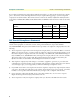
Compliance Information Model 3125 RAS Getting Started Guide In accordance with FCC rules and regulation CFR 47 68.218(b)(6), you must notify the telephone company prior to disconnection. The following information may be required when applying to your local telephone company for leased line facilities. The Universal Service Order Code (USOC) is RJ48. The Facility Interface Codes (FIC) are 04DU9-BN, 04DU9-DN, 04DU9-1KN, and 04DU9-1SN. The Service Order Code (SOC) is 6.0Y.
Model 3125 RAS Getting Started Guide Compliance Information CE Notice The CE symbol on your Patton Electronics equipment indicates that it is in compliance with the Electromagnetic Compatibility (EMC) directive and the Low Voltage Directive (LVD) of the European Union (EU). A Certificate of Compliance is available by contacting Technical Support. Conformity documents of all Patton products can be viewed online at www.patton.com under the appropriate product page.
Compliance Information 10 Model 3125 RAS Getting Started Guide
About this guide This guide describes installing and configuring a Patton Electronics Model 3125 Remote Access Server (RAS). By the time you are finished with this guide, your RAS will be receiving calls and transferring data. The instructions in this guide are based on the following assumptions: • The RAS will connect to a T1, E1, or PRI line • Callers will dial-in and connect with a V.90/K56Flex/V.
About this guide Model 3125 RAS Getting Started Guide Precautions Notes and cautions, which have the following meanings, are used throughout this guide to help you become aware of potential RAS problems: Note Calls attention to important information. The shock hazard symbol and WARNING heading indicate a potential electric shock hazard. Strictly follow the warning instructions to avoid injury caused by electric shock. The alert symbol and WARNING heading indicate a potential safety hazard.
Model 3125 RAS Getting Started Guide About this guide Mouse conventions The following conventions are used when describing mouse actions: Table 2. Mouse conventions Convention Meaning Left mouse button This button refers to the primary or leftmost mouse button (unless you have changed the default configuration). Right mouse button This button refers the secondary or rightmost mouse button (unless you have changed the default configuration).
About this guide 14 Model 3125 RAS Getting Started Guide
Chapter 1 Introduction Chapter contents Model 3125 Remote Access Server overview..........................................................................................................16 Hardware overview ................................................................................................................................................18 WAN ........................................................................................................................................................
1 • Introduction Model 3125 RAS Getting Started Guide Model 3125 Remote Access Server overview The Model 3125 (see figure 1) is a central-site remote-access server with integrated modems that terminate dial-up analog and digital users. The Model 3125RC RAS combines 96 or 120 ports, RAS software, a 10/100 Ethernet port, IP routing, Frame Relay/PPP forwarding, up to 52 T1/E1 WAN ports, and a centralized webbased management system.
Model 3125 RAS Getting Started Guide 1 • Introduction Figure 2.
1 • Introduction Model 3125 RAS Getting Started Guide Hardware overview The Model 3125 RAS is a fully integrated remote access server for central site concentration of analog and digital modem calls. The 3125 Resource Card (see figure 3) is a 6U-sized CompactPCI circuit card that contains a full set of status LEDs and control port on the chassis front panel, while connections for WAN and LAN are located on the rear 3125 Transition Module. Figure 3.
Model 3125 RAS Getting Started Guide 1 • Introduction LAN The dual 10/100-Mbps Ethernet LAN ports are presented on an RJ-45 connector with an auto-sensing/fullduplex 10Base-T or 100Base-T interface. They also include: • 100Base-TX half-/full-duplex operation (100 + 100) • 10Base-T half-/full-duplex operation (10 + 10) • Auto detection and fallback • 10/100 Mbps link and status indicators Signaling Robbed-bit, R1, R2, Q.921/Q.931 Modems Up to 96/120 V.92, V.90, K56Flex, V.
1 • Introduction Model 3125 RAS Getting Started Guide Physical dimensions 3125RC Resource Card Weight: 0.8 lbs (0.35 kg) Refer to figure 4 for height, width, and depth dimensions. Figure 4.
Model 3125 RAS Getting Started Guide 1 • Introduction 3125TM Transition Module Weight: 0.45 lbs (0.2 kg) Refer to figure 4 for height, width, and depth dimensions. Figure 5.
1 • Introduction • • • • Model 3125 RAS Getting Started Guide Dial-in dynamic IP address pool management User configurable login prompts and banners Status reporting of all access server parameters Built in HTTP server for complete configuration and control using a standard Web browser Figure 6. 3125RC status LEDs LED display The front panel (see figure 6) includes LEDs for: • POWER: Green if power is being applied. Flashing if a power supply has failed. • CPU FAIL: Red if the CPU has failed.
Model 3125 RAS Getting Started Guide 1 • Introduction • WAN STATUS: Green indicates normal status at each of the four T1/E1/PRI links. Red indicates an error.
1 • Introduction Model 3125 RAS Getting Started Guide Software overview The Patton Model 3125 supports all common remote access services as well as integrated routing and forwarding (see table 3). Authentication and network management offer control and detailed monitoring from any web browser. From the PSTN, the Model 3125 RAS will accept either T1/E1 or PRI connections, with support for both channel associated or common channel signaling. Table 3.
Chapter 2 Hardware installation Chapter contents Introduction ..........................................................................................................................................................26 Unpacking the Model 3125 RAS...........................................................................................................................26 Materials and Tools Required.............................................................................................................
2 • Hardware installation Model 3125 RAS Getting Started Guide Introduction This chapter contains the following procedures for installing the Model 3125 RAS: • “Unpacking the Model 3125 RAS”—lists the contents of the RAS shipping container • “Model 3125 installation” on page 27—describes installing the RAS in a cPCI rack.
Model 3125 RAS Getting Started Guide 2 • Hardware installation Model 3125 installation The resource and transition modules can easily be damaged by electrostatic discharge (ESD) resulting from the build-up of electrical potential on clothing and other materials. To avid damaging the 3125 modules, perform the following safety and ESD preventive measures: • Attach a ground strap to your wrist when connecting, disconnecting, or handling the modles. Connect the other end of the strap to a grounded surface.
2 • Hardware installation Model 3125 RAS Getting Started Guide 4. Press on the red tab on each injection/ejection handle to release the handle (see figure 7). Figure 7. Releasing a injection/ejection handle 5. Locate the slot where the 3125TM will be installed. Insert the 3125TM so it enters the corresponding top and bottom slot guides as shown in figure 8. Figure 8.
Model 3125 RAS Getting Started Guide 2 • Hardware installation 6. Carefully slide the 3125TM into the chassis until it engages the mid-plane (see figure 9), when that happens, pivot the injection/ejection handles into locked position (see figure 10). Verify that the red tab in each handle clicks into place, indicating that the module is fully seated and locked. Figure 9. 3125RC and 3125TM installation diagram Figure 10.
2 • Hardware installation Model 3125 RAS Getting Started Guide 7. Verify that the module is properly seated, then secure it to the chassis using the captive fasteners located adjacent to the injection/ejection handles (see figure 11). Figure 11. Securing the captive fasteners Installing the 3125RC Resource Card 1. If there is not a slot filler panel installed, go to step 2. Otherwise, remove the two screws (located at the top of the filler panel and at the bottom) that secure the panel to the card cage.
Model 3125 RAS Getting Started Guide 2 • Hardware installation Cable installation This section describes installing the network interface cables. Connecting the Ethernet ports The 3125TM has a dual 10/100 Ethernet interface for connection to your LAN (see figure 12). The Ethernet port will autosense the correct speed of the local LAN and automatically negotiate half- or full-duplex operation. This section describes connecting the RAS to the Ethernet LAN via an Ethernet hub, switch, or workstation.
2 • Hardware installation Model 3125 RAS Getting Started Guide Connecting the 10/100Base-T Ethernet port to an Ethernet switch or hub The 10/100Base-T Ethernet port (see figure 12 on page 31) is designed to connect to an Ethernet switch or hub. Connect a straight-through CAT-5 cable (one wired as shown in figure 13) between the RAS and the hub/switch. Figure 13.
Model 3125 RAS Getting Started Guide 2 • Hardware installation Connecting to the T1/E1/PRI WAN ports An active T1/E1/PRI is not necessary to configure the RAS. However, an active T1/E1/PRI connection is required to receive or make calls. The factory-set default configuration of the access server has the T1/E1 ports disabled. Note The cable connecting the T1/E1/PRI WAN ports to the RJ-48C termination jack should be CAT-3 or higher and extend no farther than 1 mile from the digital services termination.
2 • Hardware installation 34 Model 3125 RAS Getting Started Guide Completing the hardware installation
Chapter 3 Configuring the RAS for operation Chapter contents Introduction ..........................................................................................................................................................36 Configuration prerequisites ...................................................................................................................................36 Preparing the RAS for configuration..................................................................................
3 • Configuring the RAS for operation Model 3125 RAS Getting Started Guide Introduction This chapter contains the following procedures for configuring the Model 3125 Remote Access Server for operation: • “Configuration prerequisites”—lists the items you need to have on hand before configuring the RAS. • “Preparing the RAS for configuration”—describes setting up the RAS IP address and netmask parameters.
Model 3125 RAS Getting Started Guide 3 • Configuring the RAS for operation – 8 bits – No Parity – 1 Stop bit – No flow control 3. Set up HyperTerminal™ as follows: – Open a HyperTerminal session. – Enter a name for this connection. – Click on the Connect using: pop-up menu and choose the Direct to ComX option (where X is the number of the COM port onto which you connected the cable in step 1) (see figure 17). Figure 17. Hyperterminal properties – Configure the COM port settings as shown in figure 18.
3 • Configuring the RAS for operation Model 3125 RAS Getting Started Guide Figure 18. COM properties Figure 19. Terminal keys configuration – Configure the Settings for Function, arrow and ctrl keys act as to Terminal keys as shown in figure 19. 4. 38 Press to display the login window, which will resemble that shown in figure 20.
Model 3125 RAS Getting Started Guide 3 • Configuring the RAS for operation Figure 20. Login window 5. Type superuser as the default username and password, then press . The Top Level Management window displays (see figure 21). Figure 21. VT-100 Top Level Management window 6. Select option g Ethernet. 7. Select a PrimaryIpAddress to set the Ethernet A IP address. 8. Type the IP address at the > prompt, then press . 9. Use the left arrow key to return to the previous menu. 10.
3 • Configuring the RAS for operation Model 3125 RAS Getting Started Guide 16. Use the left arrow key to return to the top level management page. 17. Select a Home. 18. Select 1 StoreConfig to save your IP address and netmask. The RAS is now prepared for configuration using a Web browser. Note The default gateway has not been configured at this time. You can access the web pages with a PC located on the same network as the RAS or you must configure the default gateway using HyperTerminal.
Model 3125 RAS Getting Started Guide 3 • Configuring the RAS for operation Figure 22.
3 • Configuring the RAS for operation Model 3125 RAS Getting Started Guide Home page overview The HOME window is divided into two panes: the Configuration Menu pane and the configuration/information pane (see figure 23). The Configuration Menu contains the links to the various RAS subsystems, while the configuration/information pane is where you can view status and other information, or make changes to the system configuration.
Model 3125 RAS Getting Started Guide 3 • Configuring the RAS for operation From the Home page, the following actions can be performed: • Record Current Configuration—clicking on this button (figure 24) causes the current configuration to be stored in FLASH memory. Any changes made to the RAS configuration are stored in non-volatile RAM first. This allows the user to set the box up with a working configuration before committing it to FLASH.
3 • Configuring the RAS for operation Model 3125 RAS Getting Started Guide Configuring simple authentication The following sections describe two methods for configuring simple authentication to test the setup. No Validation A No Validation authentication setting means that the user will be able to log in without requiring a username or password. 1. Select Authentication on the Configuration Menu. The Authentication window displays (see figure 25). Figure 25.
Model 3125 RAS Getting Started Guide 3 • Configuring the RAS for operation Figure 26. Authentication Configuration window 2. Click on Modify. The Authentication Configuration window appears (see figure 26). 3. Change Validation to noValidation(0). 4. Click on the Submit Query button. A Static User The Static User authentication setting means that the user will have to use the static username and password you create to log in. 1. Select Authentication on the Configuration Menu.
3 • Configuring the RAS for operation Model 3125 RAS Getting Started Guide 2. To add an entry in the static user database (see figure 27), fill in the ID with a number not currently in use. Figure 27. Static User Identification window 3. Add the desired username and password. 4. Click on the Submit Query button. 5. Click on Modify. The Authentication Configuration window appears (see figure 26 on page 45). 6. Change Validation to StaticUsers(1). 7. Click on the Submit Query button.
Model 3125 RAS Getting Started Guide 3 • Configuring the RAS for operation 2. Click on Modify. The Modify Dial-In window appears (see figure 29). Figure 29. Modify Dial-In window, Login section 3. The IP address pool contains the IP addresses that are assigned dynamically to the dial-in connections. Type the IP address pool in the space provided.
3 • Configuring the RAS for operation Model 3125 RAS Getting Started Guide Figure 30. Modify Dial-In window, Domain Name Server section 6. Enter in the IP Address of the primary and secondary domain name servers (DNS). The DNS enables users to find locations on the Internet. 7. Click on Submit Query. Configuring the default gateway Do the following to add the default gateway (if it was not already configured through HyperTerminal): 1.
Model 3125 RAS Getting Started Guide 3 • Configuring the RAS for operation Configuring line settings and signaling for E1 1. Select T1/E1 Link on the Configuration Menu. The T1/E1 Link Activity window appears (see figure 32). Figure 32. T1/E1 Link Activity window 2. Link: 1 corresponds to Line 1 on the RAS. This is the primary link for dial-in callers. Under Link 1, Click on Configuration then Modify. The Line Interface Settings section of the WAN Circuit Configuration window appears (see figure 33).
3 • Configuring the RAS for operation Model 3125 RAS Getting Started Guide Configuring the line settings 1. Click on the Line Type pop-up menu (see figure 33 on page 49) and choose from the following options: – For an E1/PRI line your options will be either dsx1E1(4) or dsx1E1-CRC(5) – For an E1/R2 line your options will be either dsx1E1-MF(6) or dsx1E1-CRC-MF(7) 2. Click on the Line Coding pop-up menu (see figure 33 on page 49) and choose either dsx1AMI(5) or dsxHDB3(3). Most installations will use HDB3.
Model 3125 RAS Getting Started Guide 3 • Configuring the RAS for operation Figure 35. WAN Circuit Configuration window, signaling Settings section Setting the line signaling for an E1/PRI (ISDN) line Do the following: 1. Scroll down the WAN Circuit Configuration window, until the Signaling Settings section appears (see figure 35). 2. Click on the Signal Mode pop-up menu and choose messageOriented(4). 3. Click on the Message Oriented Switch Type pop-up menu (see figure 35) and choose CTR4(3). 4.
3 • Configuring the RAS for operation Model 3125 RAS Getting Started Guide Figure 36. MFR Version 2 Modify window 5. Click on the Country pop-up menu. If your country is not available, select ituStandard(1). 6. Click on Submit. 7. Scroll down to the Interregister signaling section. 8. Type the Called Number Total Digits in the box provided. This setting tells the RAS how many digits to expect from the phone company. The called Number is the number a user dials to call into the RAS. 9.
Model 3125 RAS Getting Started Guide Note 3 • Configuring the RAS for operation The information entered into the Interregister Signaling section must match the information the telco provided. If the information entered is not the same, the RAS may not answer calls. In some installations, the phone company will send a special tone to alert that it is done sending the Calling Number. In this case, the value in the Total Digits box does not have to match the telephone company’s exactly.
3 • Configuring the RAS for operation Model 3125 RAS Getting Started Guide – dsx1D4 AT&T D4 format DS1 – For ISDN PRI service, set the line type to dsx1ESF 2. Click on the Line Coding pop-up menu (see figure 33 on page 49). The most common options are: dsx1B8ZS and dsx1AMI. For ISDN PRI service, set the line coding to dsx1B8ZS. 3. Click on the Line Build Out pop-up menu (see figure 33 on page 49) and select t1pulse0dB(1). 4. Click on the Yellow Alarm Format pop-up menu and choose linkYellowFormatBit2(1).
Model 3125 RAS Getting Started Guide 3 • Configuring the RAS for operation – For T1 lines with ESF/B8ZS this should be set to linkYellowFormatDL(2). 7. Click on Submit Query. Channel assignment This section describes configuring the RAS so it will know which channels are active. Do the following: 1. Select T1/E1 Link on the Configuration Menu. The T1/E1 Link Activity window appears (see figure 32 on page 49). 2. Click on Channel Assignment.
3 • Configuring the RAS for operation Model 3125 RAS Getting Started Guide 4. To import or export a configuration, click on Import/Export under the Configuration Menu to display the Import/Export main window (see figure 38). Figure 38. Import/Export main window 5. To export the flash configuration, click on the Export Flash link on the Import/Export main page. The access server will display text configuration information resembling that shown in figure 39. Figure 39.
Model 3125 RAS Getting Started Guide 3 • Configuring the RAS for operation To save the displayed data as a text file, select the Save option on your browser (see figure 40). For example, under Netscape, select File > Save As. A dialog box will display enabling you to save the contents of the export parameters to a text file. Select the location where you want the file stored, type a file name, and click Save. Figure 40.
3 • Configuring the RAS for operation Note Model 3125 RAS Getting Started Guide If the RAS does not respond as described, the most likely cause is that the RAS default settings are not compatible with the T1/E1 line. If this is the case, use the RS-232 CONFIG port to correct the RAS settings. You will have to examine the T1/E1 Link section in the configuration pages in the RAS. 6.
Chapter 4 Operation and shutdown Chapter contents Introduction ..........................................................................................................................................................60 Activating the RAS ................................................................................................................................................60 De-activating the RAS ......................................................................................................
4 • Operation and shutdown Model 3125 RAS Getting Started Guide Introduction This chapter describes how to start or power-down the RAS. Activating the RAS Power to the modules is delivered from the cPCI chassis backplane through the 47-pin PICMG 2.11 power connectors on the 3125RC. Upon insertion in the cPCI chassis, the Model 3125 immediately powers up and begins its boot cycle. During the boot cycle, the following occurs on the 3125RC Resource Card: 1.
Model 3125 RAS Getting Started Guide 4 • Operation and shutdown 5. Use a Phillips screwdriver to loosen the captive fasteners on the 3125TM (see figure 11 on page 30) until the fasteners no longer attach the module to the rack. 6. Press the red tab on each injection/ejection handle to release the handles (see figure 7 on page 28). 7. Slide the module from the rack and place it in an anti-static bag. The RAS has been de-activated.
4 • Operation and shutdown 62 Model 3125 RAS Getting Started Guide De-activating the RAS
Chapter 5 Contacting Patton for assistance Chapter contents Introduction ..........................................................................................................................................................64 Contact information..............................................................................................................................................64 Warranty Service and Returned Merchandise Authorizations (RMAs).....................................................
5 • Contacting Patton for assistance Model 3125 RAS Getting Started Guide Introduction This chapter contains the following information: • “Contact information”—describes how to contact PATTON technical support for assistance. • “Warranty Service and Returned Merchandise Authorizations (RMAs)”—contains information about the RAS warranty and obtaining a return merchandise authorization (RMA). Contact information Patton Electronics offers a wide array of free technical services.
Model 3125 RAS Getting Started Guide 5 • Contacting Patton for assistance Return for credit policy • Less than 30 days: No Charge. Your credit will be issued upon receipt and inspection of the equipment. • 30 to 60 days: We will add a 20% restocking charge (crediting your account with 80% of the purchase price). • Over 60 days: Products will be accepted for repairs only. RMA numbers RMA numbers are required for all product returns.