
Installation Instructions

Page 3 of 7
ASSEMBLY INSTRUCTIONS (continued)
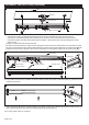
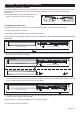
2. Remove the set screws on each side and then detach the aluminum plate. Remove the hardware pack from fixture,
unplug two connectors to separate the terminal wires and grounding wire inside the fixture plate(A).
2
4.
4
3.Remove three wire connectors from three wires, then thread these three wires through the center hole of fixture plate(A).
Wire Connector
3
AA
AA
A
Outlet Box
Aluminium Plate
LED Strip
Female Connector
Male Connector
Female Connector
Grounding Wire
Terminal Wire
Wire Connector
Male Connector
Fixture Plate
Set Screw
BBBB
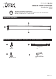
43.75 in for (#348-0102)
19.75 in for (#348-0101)
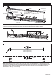
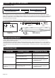
Make two spots on the ceiling 19.75 in. apart at both ends of the outlet box(#348-0101),or make two spots on the
ceiling 43.75 in. apart at both ends of the outlet box(#348-0102) for the mounting two anchors(AA).Drill holes at the
two anchor location. Hammer the anchors(AA) into the hole tightly.Attach two dry wall screws(BB) to the anchor,
thread them in part way: 2 to 3 turns only.