
Installation Instructions


PREPARATION
Before beginning assembly, installation or operation of product, make sure all parts are present. Compare parts with
package contents list and diagram on previous page. If any part is missing or damaged, do not attempt to assemble,
install or operate the product.
Tools Required for Assembly (not included): Screwdriver, Phillips Screwdriver, Pliers, Electrical Tape, Wire Cutters,
Safety Glasses, Ladder, Wire Stripper.
Page 2 of 3
ASSEMBLY INSTRUCTIONS
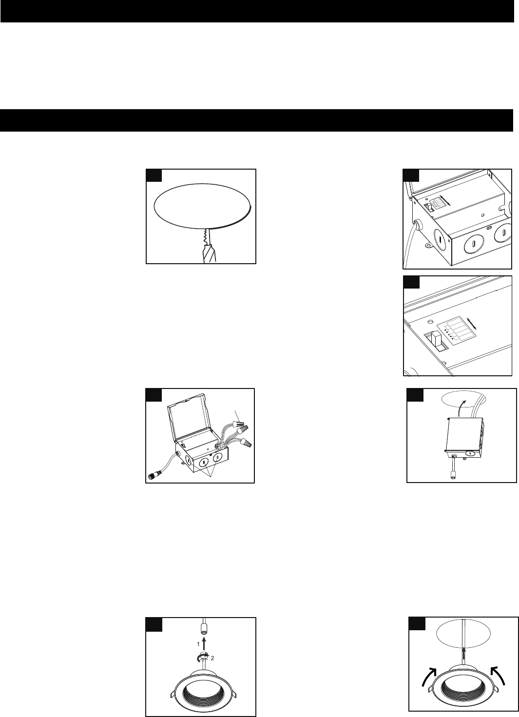
4. Insert hardwire box through
the mounting hole.
5. Connect the male plug to the
female plug and secure the
connector.
6. Push spring loaded clips on
the fixture upwards and insert
fixture base into the mounting
hole. Release the clips to
secure the fixture to the ceiling.
Turn off the power at fuse or circuit box.
Turn on the power at fuse or circuit box.
2. Open the hardwire box cover.
Adjust the color temperature
(2700K/3000K/3500K/4000K/
5000K) according to your
preference.
3. Connect electrical wires.
● Remove the appropriate
knock-out (s) to
accommodate the type of
electrical service to be used.
● Insert electrical supply cable
through knock-out into the
hardwire box.
● Use wire connector connect
ground wire of cable to ground wire on fixture.
Connect black wire of cable to black wire of fixture.
Connect white wire of cable to white wire of fixture.
● Place all wires and connections back to the hardwire box
and replace cover.
Note: Supply wire insulation must be rated for at least 90˚C.
1. Locate a suitable position to
place the fixture and open in
accordance to the cut-hole
dimensions.
A template is provided to
assist in properly locating and
cutting the hole.
1
4
5
3
6
191101
5
0
0
0
K
4
0
0
0
K
3
5
0
0
K
3
0
0
0
K
2
7
0
0
K
Five Way Switch
2a
5
0
0
0
K
4
0
0
0
K
3
5
0
0
K
3
0
0
0
K
2
7
0
0
K
Five Way Switch
2b
Knock-Out
Wire Connector