
Installation Instructions

Question/Comment/Missing Part?
Customer Service 1-800-205-6201
WARNI NG:
TO AVOID RISK OF ELECTRICAL SHOCK
TURN OFF OR DISCONNECT FROM POWER
WHILE INSTALLING OR SERVICING UNIT
Installation Instructions: 351-0018 (M-FP-7S-W) | 7.5" 1000 Lumen LED Square Flat Panel Light
INSTALLATION INSTRUCTIONS (For Can)
1. If you want to install one of the provided trims; place the trim over the front face of the LED light
and bend the clips around the back to latch it in place.
2. Safety Concern! Always turn off the power at the breaker when installing light xtures.
3. Before installing, use the Color Temperature Guide Card select whichever color temperature best
ts your environment with the selector on the back of the light.
4. Screw the male E26 adapter (DD) into the socket of the recessed can. Refer to Fig. 1.
5. Connect the E26 adapter (DD), to the stripped wires (EE) using the quick connect. Refer to Fig 2.
6. Attach the torsions springs (CC) to the mounting plate (BB), using the mounting screws (JJ).
Refer to Fig. 3. Then attach the mounting plate (BB) to the LED xture (AA). Refer to Fig. 4.
7. Compress the torsion springs (CC). Then slide the light into the recessed can making sure that
the torsion springs expanding into the mounting brackets within the can. Refer to Fig 5.
4
5-6 In. Recessed Can Installation
6
Installing the fixture
□ Insert the torsion springs into the fixture housing brackets
.
□ When installing trim into a 5 in. recessed housing, the torsion
spring (FF) must be moved. Unscrew the torsion spring (FF) from
the 6 in. position and move it to the 5 in. position (See Fig. 4).
□ Gently push the fixture into the recessed housing (See Fig. 5).
1
Turning Off the Power
2
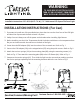
Choosing a color temperature
before installing
□ Turn the power OFF at the switch and
fusebox or the circuit breaker.
□ Remove the existing trim installed in the
recessed housing.
□ Use the slide switch to choose a color
temperature before installing. Soft White
(SW), Bright White (BW), Daylight (DL) or
choose to adjust the color temperature
from the wall switch (SWITCH) (See Fig. 1).
□ Install the E26 adapter (DD) into the socket (See Fig. 2).
3
Installing the adapter
□ Connect the two terminals together (See Fig. 3).
4
Connecting the terminals
5
Adjusting the torsion springs
Soft White
3000K
Bright White
4000K
Daylight
5000K
Switch*
Fig. 1
Connect the orange connectors
5”
6”
Move the torsion spring from the 6 in.
position to the 5 in. position
FF
Fig. 3
Fig. 4
Fig. 5
Fig. 2
1.
2.
4
5-6 In. Recessed Can Installation
6
Installing the fixture
□ Insert the torsion springs into the fixture housing brackets.
□ When installing trim into a 5 in. recessed housing, the torsion
spring (FF) must be moved. Unscrew the torsion spring (FF) from
the 6 in. position and move it to the 5 in. position (See Fig. 4).
□ Gently push the fixture into the recessed housing (See Fig. 5).
1
Turning Off the Power
2
Choosing a color temperature
before installing
□ Turn the power OFF at the switch and
fusebox or the circuit breaker.
□ Remove the existing trim installed in the
recessed housing.
□ Use the slide switch to choose a color
temperature before installing. Soft White
(SW), Bright White (BW), Daylight (DL) or
choose to adjust the color temperature
from the wall switch (SWITCH) (See Fig. 1).
□ Install the E26 adapter (DD) into the socket (See Fig. 2).
3
Installing the adapter
□ Connect the two terminals together (See Fig. 3).
4
Connecting the terminals
5
Adjusting the torsion springs
Soft White
3000K
Bright White
4000K
Daylight
5000K
Switch*
Fig. 1
Connect the orange connectors
5”
6”
Move the torsion spring from the 6 in.
position to the 5 in. position
FF
Fig. 3
Fig. 4
Fig. 5
Fig. 2
5.
3.
4
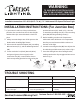
5-6 In. Recessed Can Installation
6
Installing the fixture
□ Insert the torsion springs into the fixture housing brackets.
□ When installing trim into a 5 in. recessed housing, the torsion
spring (FF) must be moved. Unscrew the torsion spring (FF) from
the 6 in. position and move it to the 5 in. position (See Fig. 4).
□ Gently push the fixture into the recessed housing (See Fig. 5).
1
Turning Off the Power
2
Choosing a color temperature
before installing
□ Turn the power OFF at the switch and
fusebox or the circuit breaker.
□ Remove the existing trim installed in the
recessed housing.
□ Use the slide switch to choose a color
temperature before installing. Soft White
(SW), Bright White (BW), Daylight (DL) or
choose to adjust the color temperature
from the wall switch (SWITCH) (See Fig. 1).
□ Install the E26 adapter (DD) into the socket (See Fig. 2).
3
Installing the adapter
□ Connect the two terminals together (See Fig. 3).
4
Connecting the terminals
5
Adjusting the torsion springs
Soft White
3000K
Bright White
4000K
Daylight
5000K
Switch*
Fig. 1
Connect the orange connectors
5”
6”
Move the torsion spring from the 6 in.
position to the 5 in. position
FF
Fig. 3
Fig. 4
Fig. 5
Fig. 2
4.
Page 3
previous
by
ANY
electrical
Team at
your
TOOLS REQUIRED FOR INSTALLATION AND ASSEMBLY (not
WIRE STRIPPERS
Question/Comment/Missing Part?
Customer Service 1-800-205-6201
WARNING:
TO AVOID RISK OF ELE CTRICAL SHOCK
TURN OFF OR DISCONNECT FROM POWER
WHILE INS TALLING OR SE RVICING UNIT
Installation Instructions: 351-0018 (M-FP-7S-W) | 7.5" 1000 Lumen LED Square Flat Panel Light
INSTALLATION INSTRUCTIONS (For Can)
1.
2. Before installing, use the Color Temperature Guide Card select whichever color temperature best
fits your environment with the selector on the back of the light.
3. Screw the male E26 adapter (DD) into the socket of the recessed can. Refer to Fig. 1.
4. Connect the E26 adapter (DD), to the stripped wires (EE) using the quick connect. Refer to Fig 2.
5. Attach the torsions springs(CC) to the light fixture(AA),using the mounting screws(JJ)
Refer to Fig. 3
6. Compress the torsion springs (CC). Then slide the light into the recessed can making sure that
the torsion springs expanding into the mounting brackets within the can. Refer to Fig 4.
4
6
Installing the fixture
□ Insert the torsion springs into the fixture housing brackets
□ When installing trim into a 5 in. recessed housing, the torsion
spring (FF) must be moved. Unscrew the torsion spring (FF) from
the 6 in. position and move it to the 5 in. position (See Fig. 4).
□ Gently push the fixture into the recessed housing (See Fig. 5).
2
Choosing a color temperature
before installing
□ Use the slide switch to choose a color
temperature before installing. Soft White
(SW), Bright White (BW), Daylight (DL) or
choose to adjust the color temperature
from the wall switch (SWITCH) (See Fig. 1).
□ Install the E26 adapter (DD) into the socket (See Fig. 2).
3
Installing the adapter
5
Adjusting the torsion springs
Soft White
3000K
Bright White
4000K
Daylight
5000K
Switch*
Fig. 1
Connect the orange connectors
5”
6”
Move the torsion spring from the 6 in.
position to the 5 in. position
FF
Fig. 4
Fig. 5
Fig. 2
1.
4
6
Installing the fixture
□ Insert the torsion springs into the fixture housing brackets
□ When installing trim into a 5 in. recessed housing, the torsion
spring (FF) must be moved. Unscrew the torsion spring (FF) from
the 6 in. position and move it to the 5 in. position (See Fig. 4).
□ Gently push the fixture into the recessed housing (See Fig. 5).
2
Choosing a color temperature
before installing
□ Turn the power OFF at the switch and
fusebox or the circuit breaker.
□ Remove the existing trim installed in the
recessed housing.
□ Use the slide switch to choose a color
temperature before installing. Soft White
(SW), Bright White (BW), Daylight (DL) or
choose to adjust the color temperature
from the wall switch (SWITCH) (See Fig. 1).
□ Install the E26 adapter (DD) into the socket (See Fig. 2).
3
Installing the adapter
□ Connect the two terminals together (See Fig. 3).
5
Adjusting the torsion springs
Soft White
3000K
Bright White
4000K
Daylight
5000K
Switch*
Fig. 1
Connect the orange connectors
5”
6”
Move the torsion spring from the 6 in.
position to the 5 in. position
FF
Fig. 3
Fig. 4
Fig. 5
Fig. 2
2.
4.3.
5-6 In. Recessed Can Installation
□ Insert the torsion springs into the fixture housing brackets.
□ When installing trim into a 5 in. recessed housing, the torsion
spring (FF) must be moved. Unscrew the torsion spring (FF) from
the 6 in. position and move it to the 5 in. position (See Fig. 4).
□ Connect the two terminals together (See Fig. 3).
4
Connecting the terminals
5
Adjusting the torsion springs
Fig.
3
Fig. 4
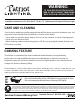
BB CC DD EE
HH II JJ KK LL
Quantity
1
1
5 & 6 in. Torsion spring brackets 2
E26 adapter with male connector 1
Stripped wires with male connector 1
2
1
1
2
Hardware not shown to actual size.