
Installation Instructions

Question/Comment/Missing Part?
Customer Service 1-800-205-6201
WARNI NG:
TO AVOID RISK OF ELECTRICAL SHOCK
TURN OFF OR DISCONNECT FROM POWER
WHILE INSTALLING OR SERVICING UNIT
Installation Instructions: 351-0001 (M-FP-11R-W) | 11" 1700 Lumen LED Round Flat Panel Light
- When using product, basic precautions should always be followed.
- Read and follow these instructions and heed all warnings.
- Carefully read and understand the information given in this manual
before beginning installation. Failure to do so could lead to electric
shock, fire, or other injuries which could be hazardous or even fatal.
- Save these instructions and warnings.
- Use carabiner hook to hang product, do not use the electrical cord.
- Do not install on radiant heated ceiling.
- This item is designed for dry use and is not water proof.
- Do not place this item in a humid or dusty environment.
- Do not use in areas with temperature higher than 104° Fahrenheit.
- Do not use in areas near a gas source.
WARNING
CAUTION
PRE-INSTALLATION:
1. Before assembly, compare package contents
with parts list to make sure all parts are present.
2. Shut off power at circuit breaker before removing existing fixture. If you are unfamiliar with electrical
installations, we recommend you have a qualified electrition complete your intallation.
3. Select suitable location that can support the weight of the fixture. Determine mounting method (Page 2).
4. Mark two spots on the ceiling 42” apart for the mounting hardware (not included).
Measuring Tape
TOOLS REQUIRED:
Power Drill
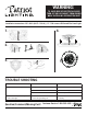
HARDWARE:
Part Description Quantity
AA Chain 2
BB “S” Hook 2
AA
BB
Question/Comment/Missing Part?
Customer Service 1-800-205-6201
WARNI NG:
TO AVOID RISK OF ELECTRICAL SHOCK
TURN OFF OR DISCONNECT FROM POWER
WHILE INSTALLING OR SERVICING UNIT
Assembly & Installation Instructions: 370-5439 | 10ft LED String Light
PRE-INSTALL
HARDWARE
Tools required
1. Before assembly compare package contents with list to make sure
all parts are present.
2. Shut off power at circuit breaker before removing existing xture. If
you are unfamiliar with electrical installations, we recommend you
have a qualied electrician complete your installation.
3. Select suitable location that can support the weight of the xture.
Determine mounting method (Page 2.).
4. Using the Color Temperature Guide Card select whichever color
temperature best ts your environment
3 HOMEDEPOT.COM
Please contact 1-877-527-0313 for further assistance.
Phillips
screwdriver
AA BB CC DD EE
FF GG
HH II JJ KK LL
Part Description Quantity
AA 7.5 in. fixture 1
BB Mounting bracket 1
CC 5 & 6 in. Torsion spring brackets 2
DD E26 adapter with male connector 1
EE Stripped wires with male connector 1
FF 5 & 6 in. Torsion springs 2
GG Ground wire 1
HH Ground wire screw 1
II J-Box mounting screws 2
JJ Wire nuts 3
KK 5 & 6 in. Torsion spring screws 2
LL 5 & 6 in. Torsion bracket mounting screws 4
Pre-Installation
TOOLS REQUIRED
HARDWARE INCLUDED
NOTE: Hardware not shown to actual size.
Part Description Qty
EE Drywall Anchor 3
FF Drywall Screw 3
GG Black Trim 1
HH Brushed Nickel Trim 1
Part Description Qty
AA 15 Inch Light 1
BB Mounting Bracket 1
CC Mounting Screws 2
DD Wire Nuts 3
AA
3 HOMEDEPOT.COM
Please contact 1-877-527-0313 for further assistance.
Phillips
screwdriver
AA BB CC DD EE
FF GG
HH II JJ KK LL
Part Description Quantity
AA 7.5 in. fixture 1
BB Mounting bracket 1
CC 5 & 6 in. Torsion spring brackets 2
DD E26 adapter with male connector 1
EE Stripped wires with male connector 1
FF 5 & 6 in. Torsion springs 2
GG Ground wire 1
HH Ground wire screw 1
II J-Box mounting screws 2
JJ Wire nuts 3
KK 5 & 6 in. Torsion spring screws 2
LL 5 & 6 in. Torsion bracket mounting screws 4
Pre-Installation
TOOLS REQUIRED
HARDWARE INCLUDED
NOTE: Hardware not shown to actual size.
BB
CC
3 HOMEDEPOT.COM
Please contact 1-877-527-0313 for further assistance.
Phillips
screwdriver
AA BB CC DD EE
FF GG
HH II JJ KK LL
Part Description Quantity
AA 7.5 in. fixture 1
BB Mounting bracket 1
CC 5 & 6 in. Torsion spring brackets 2
DD E26 adapter with male connector 1
EE Stripped wires with male connector 1
FF 5 & 6 in. Torsion springs 2
GG Ground wire 1
HH Ground wire screw 1
II J-Box mounting screws 2
JJ Wire nuts 3
KK 5 & 6 in. Torsion spring screws 2
LL 5 & 6 in. Torsion bracket mounting screws 4
Pre-Installation
TOOLS REQUIRED
HARDWARE INCLUDED
NOTE: Hardware not shown to actual size.
DD
3 HOMEDEPOT.COM
Please contact 1-877-527-0313 for further assistance.
Phillips
screwdriver
AA BB CC DD EE
FF GG
HH II JJ KK LL
Part Description Quantity
AA 7.5 in. fixture 1
BB Mounting bracket 1
CC 5 & 6 in. Torsion spring brackets 2
DD E26 adapter with male connector 1
EE Stripped wires with male connector 1
FF 5 & 6 in. Torsion springs 2
GG Ground wire 1
HH Ground wire screw 1
II J-Box mounting screws 2
JJ Wire nuts 3
KK 5 & 6 in. Torsion spring screws 2
LL 5 & 6 in. Torsion bracket mounting screws 4
Pre-Installation
TOOLS REQUIRED
HARDWARE INCLUDED
NOTE: Hardware not shown to actual size.
EE FF
Phillips Screw Driver
Page 3
CAUTION:
1. Before starting installation of this fixture or removal of a previous
fixture, disconnect the power by turning off the circuit breaker or by
removing the fuse at the fuse box.
2. CONSULT A QUALIFIED ELECTRICIAN IF YOU HAVE ANY
ELECTRICAL QUESTIONS. If you have any non-electrical
questions about this fixture, please call our Customer Service Team at
1-877-527-0313 or visit www.homedepot.com. Please reference your
SKU (204-960) or UPC (046335960640).
3. KEEP your receipt and these Instructions for Proof of Purchase.
TOOLS REQUIRED FOR INSTALLATION AND ASSEMBLY (not
included):
ELECTRICAL TAPE
SAFETY
GOOGLES
WIRE STRIPPERSWIRE CUTTERS
#2 PHILIPS
SCREWDRIVER
FLATHEAD
SCREWDRIVER
Power Drill
3 HOMEDEPOT.COM
Please contact 1-877-527-0313 for further assistance.
Pre-Installation
TOOLS REQUIRED
HARDWARE INCLUDED
NOTE: Hardware not shown to actual size.
Part Description Quantity
AA Mounting Plate (8.07 in. x 9.8 in. x 0.47 in.) 1
BB 3/16 in. Toggle Bolts 4
CC Wire Nuts 3
DD Screws #8-32 x 1 in. 2
Phillips
screwdriver
AA BB CC DD
Power Drill 1/2 in. Drill Bit
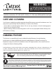
DISTANCE
3 FT.
5 FT.
8 FT.
15 FT.
CENTER BEAM (FOOT CANDLES)
LIGHTING DISTRIBUTION
39
14
5.5
1.6
BEAM ANGLE = 112º
BEAM DIAMETER
8.9 FT.
15 FT.
24 FT.
44 FT.
5/16” Drill Bit
3 HOMEDEPOT.COM
Please contact 1-877-527-0313 for further assistance.
Pre-Installation
TOOLS REQUIRED
HARDWARE INCLUDED
NOTE: Hardware not shown to actual size.
Part Description Quantity
AA Mounting Plate (8.07 in. x 9.8 in. x 0.47 in.) 1
BB 3/16 in. Toggle Bolts 4
CC Wire Nuts 3
DD Screws #8-32 x 1 in. 2
Phillips
screwdriver
AA BB CC DD
Power Drill 1/2 in. Drill Bit
DISTANCE
3 FT.
5 FT.
8 FT.
15 FT.
CENTER BEAM (FOOT CANDLES)
LIGHTING DISTRIBUTION
39
14
5.5
1.6
BEAM ANGLE = 112º
BEAM DIAMETER
8.9 FT.
15 FT.
24 FT.
44 FT.
GG HH