
Installation Instructions
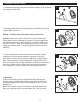

4. Mounting
Place fixture canopy (A) over the gem bar (AA) and align the
mounting holes on both sides of the canopy. Secure the fixture
using two canopy screws (DD). Restore power at fuse or circuit
breaker box.
Note: LED module on the swivel head is non-replaceable from
base (A). Head can tilt 90˚ max and rotate 350˚ max of motion.
3
2
1
A
CC
1. Separate the gem bar (AA) from the fixture canopy (A) by removing
two canopy screws (DD).
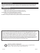
3. Connect the power source ground wire to the green or bare
copper wire from the fixture assembly. Using wire nuts (CC)
(provided), connect white (N) power supply wire to white fixture
lead. Connect black (L) power supply wire to black fixture lead.
Do not mix wires. Pull on each wire lead to make sure connections
are secure. Make certain no bare wires are exposed outside of
wire connectors. Tuck all connections neatly into junction box.
2. Mount gem bar (AA) to the junction box (not included) using two
screws (BB) to secure it.
Wiring – all wiring must take place inside junction box.
Caution: Make sure power is off at fuse or circuit breaker box.
Check power wires for damage or scrapes. If power supply wires
are within three inches of the LED driver, use wire suitable for at
least 90°C (194°F). Note: Most dwellings built before 1985 have
supply wire rated to 60°C. Consult a qualified electrician before
installing.
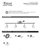
ASSEMBLY INSTRUCTIONS
3
AA
BB
AA
A
DD
DD
4
AA