
Installation Instructions

ASSEMBLY INSTRUCTIONS
4
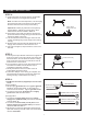
STEP 5:
a. The lanyard is provided as a means to support the
fixture from the junction box while connecting the
electrical wires. This enables the fixture to hang
from the junction box and your hands are free to
make the wire connections.
b. Turn the button stop so it may be inserted into the
crossbar slot. Make sure the button stop is
completely inside the crossbar.
c. Slowly release the fixture to make sure it is
supported by the button stop.
d. Proceed to Step 8. Once wiring is complete, the
lanyard will push into the junction box when the
Ceiling Canopy is Attached to the ceiling.
Crossbar Assembly
Button Stop
Lanyard
Slot
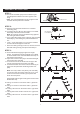
STEP 4:
a. Confirm that the mounting height is acceptable.
Refer to STEP 3 if changes are required.
: To make the next step easier, cut the supply
wire and ground wire 24 inches longer than the
distance from the fixture loop to the ceiling.
: Please pay attention to the polarity
(wires labels L & N) when cutting wires. Wire
identification will be needed in STEP 6.
b. Pass supply wires and ground wire through the
quick link and the ceiling canopy and remove any
remaining slack in the wire.
c. Trim excess fixture wire leaving a minimum of 6
inches extending beyond the edge of the ceiling
canopy.
d. Separate the smooth side and ribbed side of the
supply wire to about 3 inches from the end.
e. Using wire strippers, strip each wire ½ inch from
the end.
Note
Important
Supply Wires
and Ground Wire
STEP 6:
* Use Wire Connectors (supplied) to connect the
wires.
ground wire green ground
screw
ground screw
ground wire supply
ground
house white wire fixture
supply wire (ribbed sided)
house black (or red) wire
fixture supply wire (smooth side)
outlet box
a) Ground Wire:
1. Wrap supply around
on mounting bracket, no less than 2 in.
from the end of the wire. Tighten .
2. Connect fixture green to
wire with wire connector.
b) Supply Wire:
1. Connect the to the
from fixture identified
with the label “N”.
2. Connect the to the
from fixture
identified with the label “L”.
3. Wrap each connection with approved electrical
tape and carefully stuff all of the connected wires
into the .
WHITE OR RIBBED
BLACK (OR RED) WIRE
FROM SUPPLY
FROM SUPPLY
RIBBED SIDE OF WIRE
FIXTURE
FROM
IDENTIFIED
SMOOTH SIDE OF WIRE FROM
FIXTURE IDENTIFIED
WITH THE LABEL “N”
WITH THE LABEL “L”
GROUND WIRE
GROUND WIRE
FROM SUPPLY
FROM FIXTURE
GREEN GROUND SCREW