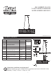
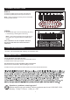
SKU NUMBER: 351-9123 7-LIGHT LINEAR CHANDELIER MODEL NUMBER: MND3381C REVISED 2017-05-27 PACKAGE CONTENTS PART DESCRIPTION QUANTITY Stock Part# AA Crossbar Assembly 1 pc BB Wire Connector 3 pcs CC Outlet Box Screw 2 pcs A Lock Ball Bulb 4 pcs N/A 7 pcs I823SC B D 913451KIT 7 pcs G13202BS D 1 pc N/A E Crystal A 36 pcs G12729CR (1pc pare part provided) 65 pcs G 13305 CR G Shade 1 pc M13301SH H Allen Wrench 1 pc N/A F Crystal B BB CC Bulb Shield ( For Halogen Bulb
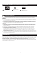
HARDWARE CONTENTS Note: Hardware not shown in actual size. AA Crossbar Assembly x1 BB Wire Connector x3 CC Outlet Box Screw x2 SAFETY INFORMATION Please read and understand this entire manual before attempting to assemble, operate or install the product. WARNING: ● Turn off electricity at main fuse box (or circuit breaker box) before beginning installation by removing fuse (or switching off circuit breaker). ● Be careful not to damage or cut the wire insulation (covering) during fixture installation.
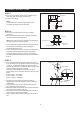
ASSEMBLY INSTRUCTIONS STEP 1: a. Secure the crossbar (AA) to the outlet box (not included) with outlet box screws (CC). b. Tighten until snug. Outlet Box AA Note: The preassembled mounting screws on the Crossbar should protrude outward. CC STEP 2: a. Remove mounting balls from the crossbar assembly. b. Fit the ceiling canopy to the crossbar assembly and secure with mounting balls. Hex Nut Note: The ceiling canopy should be snug against the ceiling and the mounting balls.
ASSEMBLY INSTRUCTIONS STEP 4: a. The lanyard is provided as a means to support the fixture from the junction box while connecting the electrical wires. This enables the fixture to hang from the junction box and your hands are free to make the wire connections. b. Turn the button stop so it may be inserted into the crossbar slot. Make sure the button stop is completely inside the crossbar (AA). c. Slowly release the fixture to make sure it is supported by the button stop. d. Proceed to Step 5 .
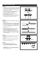
ASSEMBLY INSTRUCTIONS STEP 8: a. Attach crystals (F) to the loops at location B. b. Attach crystals (E) to the loops at location A. E Note : Hang crystals by starting on the inside and working to the outside. F STEP 9: A a. Attach Shade (G) to Fixture Assembly (D) using Lock balls (A), Hand tighten until snug. D Note : To prevent fingerprints and scratches on the shade, put on gloves before installing the shade. Your installation is now complete.
HARDWARE CONTENTS Note: Hardware not shown in actual size. AA Crossbar Assembly x1 BB Wire Connector x3 CC Outlet Box Screw x2 SAFETY INFORMATION Please read and understand this entire manual before attempting to assemble, operate or install the product. WARNING: ● Turn off electricity at main fuse box (or circuit breaker box) before beginning installation by removing fuse (or switching off circuit breaker). ● Be careful not to damage or cut the wire insulation (covering) during fixture installation.
ASSEMBLY INSTRUCTIONS STEP 1: a. Secure the crossbar (AA) to the outlet box (not included) with outlet box screws (CC). b. Tighten until snug. Outlet Box AA Note: The preassembled mounting screws on the Crossbar should protrude outward. CC STEP 2: a. Remove mounting balls from the crossbar assembly. b. Fit the ceiling canopy to the crossbar assembly and secure with mounting balls. Hex Nut Note: The ceiling canopy should be snug against the ceiling and the mounting balls.
ASSEMBLY INSTRUCTIONS STEP 4: a. The lanyard is provided as a means to support the fixture from the junction box while connecting the electrical wires. This enables the fixture to hang from the junction box and your hands are free to make the wire connections. b. Turn the button stop so it may be inserted into the crossbar slot. Make sure the button stop is completely inside the crossbar (AA). c. Slowly release the fixture to make sure it is supported by the button stop. d. Proceed to Step 5 .
ASSEMBLY INSTRUCTIONS STEP 8: a. Attach crystals (F) to the loops at location B. b. Attach crystals (E) to the loops at location A. E Note : Hang crystals by starting on the inside and working to the outside. F STEP 9: A a. Attach Shade (G) to Fixture Assembly (D) using Lock balls (A), Hand tighten until snug. D Note : To prevent fingerprints and scratches on the shade, put on gloves before installing the shade. Your installation is now complete.