Pathport Manager User’s Guide Suite 103, 1439 - 17 Avenue S.E. Calgary, AB, T2G 1J9 Canada Phone: Fax: (403) 243-8110 (403) 287-1281 E-mail: support@pathwayconnect.com www.pathwayconnect.
Pathport Manager User’s Guide Table of Contents Table of Contents..................................................................................................2 Installing Pathport Manager ..................................................................................3 Setting up your PC................................................................................................9 Starting up your Pathport System .......................................................................
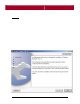
Pathport Manager User’s Guide INSTALLING PATHPORT MANAGER Windows: From CD If your computer supports Autorun, simply place the Pathport Manager CD in your CD-ROM, and the installation procedure should begin. If it does not, double click on the "pm3inst.exe" file in the root directory of the CD to begin. From a downloaded file: Download the pm3inst.exe file. From Windows Explorer, run the file, starting the installation program.
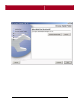
Pathport Manager User’s Guide Pressing "Next" will begin the installation process. Screen 2: Screen 2 of the installation will prompt you to specify a folder location for the installation of Pathport Manager. If you are unsure of where to install Pathport Manager, it is recommended that you install Pathport Manager in the location specified by the installer .
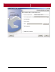
Pathport Manager User’s Guide Screen 3 allows you to specify where you would like shortcuts created for launching Pathport Manager. The default action is for the installer to create a new program group within the Windows Start Menu containing the Pathport Manager launcher. You can also specify that icons be added to the desktop, or that the launcher be placed in an existing program group.
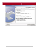
Pathport Manager User’s Guide The fourth screen is a summary of all of the configuration options given to the installer. If you wish to change any options before proceeding with the installation, you may click the Previous button to go back to the last screen. If all of the options are correct, clicking the Install button will complete the installation.
Pathport Manager User’s Guide As Pathport Manager is being installed, the installer will display its' progress. Pressing Cancel at any time during this phase will stop the installation and clean-up any installed files. This process can take a few minutes, so it is important to be patient while the installer is working.
Pathport Manager User’s Guide Once the program is installed, the installer will notify you that the process was successful, and will review where the program was installed. Pressing Done will finish the installation. You are now ready to launch Pathport Manager.
Pathport Manager User’s Guide SETTING UP YOUR PC From the factory, Pathports are configured to search the network for Pathport Manager to receive their first boot settings, as well as the latest operating software. The first step in getting the system up and running is to configure your computer's network connection for Pathport traffic. It is recommended that the Pathport network be configured to operate on the 10.x.x.x. class A internal subnet.
Pathport Manager User’s Guide Click the "Properties" button. Select the "Use the following IP address" radio button, and specify 10.0.0.5 as the IP address. Specify 255.0.0.0 for the subnet mask. Do not specify any addresses for the DNS options. These are unnecessary for Pathport Manager. Click the "OK" button to complete the setup process. You should now Start Pathport Manager. Windows 98 users: Choose to open the Windows 98 Control Panel.
Pathport Manager User’s Guide Windows 2000 users: Choose to open the network configuration dialog. Select the connection named "Local Area Connection", and from the File or Right-Click menus select "Properties". Select the "General" tab, then select "Internet Protocol (TCP/IP)". Click the "Properties" button. Select the "Use the following IP address" radio button, and specify 10.0.0.5 as the IP address. Specify 255.0.0.0 for the subnet mask.
Pathport Manager User’s Guide Linux Users: As root, enter the following: ifconfig eth0 down ifconfig eth0 netmask 255.0.0.0 10.0.0.5 ifconfig eth0 up Where eth0 is the name of your network interface. You should now Start Pathport Manager. STARTING PATHPORT MANAGER When Pathport Manager runs for the first time, it locates Network Interfaces present on the host computer and binds to the first interface found.
Pathport Manager User’s Guide The Pathport Communications Setup panel will pop up: If "10.0.0.5" is not listed in the Local IP Address box, enter it and click OK. Note: Depending on the operating system being used, it may be necessary to restart Pathport Manager before Pathport Nodes are discovered. Once Pathport Manager has been set up to communicate using the correct network interface and IP address, you can now start your Pathport System for the first time.
Pathport Manager User’s Guide STARTING UP YOUR PATHPORT SYSTEM From the factory, Pathport nodes are configured to continually re-boot until they receive new IP addresses and operating software from Pathport Manager. This is to prevent mismatched software versions, as well as conflicting network addresses. IP Addresses: Every device on a Pathport network ( or any IP network) must be assigned a unique IP address.
Pathport Manager User’s Guide 5. Re-start Pathport Manager to enable the servers. 6. Configure the BOOTP server by selecting "Pathport Communications" , then "Configure Bootp Server: 7.
Pathport Manager User’s Guide 8. Make sure that your PC's IP address is correctly noted in the "Local IP" box. If it is not, enter it and press enter. The Pathport will use the Local IP parameter to find out where to request firmware from. 9. Enter an IP range that does not include your PC's IP address. For example, if your PC's IP address is 10.0.0.5, you should enter 10.0.0.101 into the Address Range Start box, and 10.255.255.254 into the Address Range end box. 10.
Pathport Manager User’s Guide 13. Once all of your Pathports have started, you can disable the servers for future runs of Pathport Manager by de-selecting "Enable Firmware Uploads" from the "Pathport Communications" item within the tools menu.
Pathport Manager User’s Guide RUNNING PATHPORT MANAGER FOR THE FIRST TIME: The first time Pathport Manager is run, the program will require that an administrator account be created. A message box will pop up to notify you of this process.
Pathport Manager User’s Guide Pressing OK will bring up the "Manage Users" dialog: To create an administrator account, simply enter a user name, then a password. You will need to verify the password as well. This will be your login for future versions of Pathport Manager. NOTE: As of the writing of this manual, security and user management has been temporarily disabled. All features will be available to all users of Pathport Manager, regardless of administrator status. This will be changed for version 3.
Pathport Manager User’s Guide When Pathport Manager starts, it automatically queries the network for all of the connected Pathports. It then queries each unit for its' configuration information. If Pathport nodes are detected on the network, "On-line" will appear in the bottomright corner of the window. Pathport Manager's automatic discovery process should be visible in the Network Tree.
Pathport Manager User’s Guide Once all of the nodes are added to the show, it is important that each DMX input port is assigned a unique xDMX source address. (Overlapping sources will cause flickering and data contention). DMX input mapping is set up within the input map frame. To change an input's source address, simply click the input port anywhere it appears, and drag it to a different source within the xDMX Source tree.
Pathport Manager User’s Guide To connect an output to a source simply drag an output port to a universe and drop it on top of a universe. The last step is to clear the existing patch information from the nodes. The Pathports are shipped patched to the default configuration, which allows for outof-the-box performance without the need for Pathport Manager. This patch HTP merges all A inputs and connects them to all A outputs, and all B inputs to all B outputs. This is done via the "Quick Patch" system.
Pathport Manager User’s Guide AN INTRODUCTION TO PATHPORT MANAGER Introduction Welcome to Pathport Manager 3! This software will provide you with a powerful yet easy-to-use tool for managing, configuring, and testing your Pathport system. Pathport Manager and your Pathport system will help you efficiently manage lighting control data throughout your facility.
Pathport Manager User’s Guide channels at a given xDMX source address, a universe is automatically created for those channels, saving a great deal of time. What about merging and prioritizing? Pathport universes can be created using a priority system that allows up to 8 xDMX channels to be patched to a single DMX output channel. Each xDMX channel patched to an output channel has a priority level associated with it that tells the Pathport how to handle each channel.
Pathport Manager User’s Guide GETTING STARTED WITH PATHPORT MANAGER If you've plugged your PC into your Pathport network and the available nodes appear in your Network Tree in Pathport Manager, you are ready to start using Pathport Manager right away. If you don't see any nodes, you ll have to be a bit more patient and carry on with Setting Up your Computer. If you can see nodes in Pathport Manager's Network Tree, here's what you need to know for a quick start.
Pathport Manager User’s Guide To patch your nodes: 1. Click and hold on the universe you wish to patch in the Patch window. 2. Drag it over to the Available Output Ports window, until it's over the port that you wish to connect to. 3. Let go. The output port you have chosen will disappear from the available output ports window and reappear in the Patchwindow. 4. Alternatively, you can drag an Output Port to the DMX Universe you want to patch to. Either method achieves the same result.
Pathport Manager User’s Guide ADVANCED NETWORK SETUP Pathports and Pathport Manager are capable of living on any subnet, public or private. However, use of Pathports on a public network is not recommended due to large traffic volumes created by the Pathport. Due to varying complexities in computer and network configuration and setup, Pathport Manager may require additional setup before it is ready to communicate with a Pathport Network.
Pathport Manager User’s Guide The Pathport Communications Setup panel will pop up: To set the correct network interface enter the IP address of the network interface connected to the Pathport network in the Local IP Address box, then press the OK button. Pathport Manager will attempt to discover all of the Pathport nodes on the new interface as soon as the panel is closed.
Pathport Manager User’s Guide PATHPORT MANAGER'S INTERNAL WINDOWS Pathport Manager's main window consists of a number of internal panels, organized by function. This section will explain each of these in detail. System Tree: This is the panel where all of the selection of nodes is done. It also provides a system wide view of all of the Pathports currently connected to the system. This panel is separated into two tree structures, the Show Tree, and the Network Tree.
Pathport Manager User’s Guide Show Tree: The Show Tree represents all of the Pathports that are currently assigned to the show. This tree represents the current configuration for the show, but may not represent what is present on the network. The Show Tree is where all modifications to Pathport properties begin. When a Pathport is selected in the Show Tree, it is selected for editing in either the graphical editor, or the Properties window.
Pathport Manager User’s Guide Input Map: The Input Map displays the configuration of all DMX input ports connected to the system. Each input port's xDMX offset, as well as its Quick Universe number, are configured within the Input map's tree. The Input Map will also display status for all sources and quick universes, depending on the number of DMX inputs connected.
Pathport Manager User’s Guide Pathport Properties Window: This is a quick, nongraphical view of the currently selected Pathport's properties, activated by selecting "Properties" from the Pathport right-click menu. Values for all of the Pathport's configurable parameters can be changed in real time by selecting or entering a new value and pressing enter.
Pathport Manager User’s Guide Graphical Pathport Properties window: This window is a graphical look at the current configuration of the selected Pathport. It gives a quick look at the node's LCD display and soft labels, as well as allows for editing of all of the node's properties. To access the editing features of this window, right click the element that is to be edited,and a menu will pop up.
Pathport Manager User’s Guide Available Output Ports window: The Available Output Ports window contains all un-patched outputs in the show. Each output is represented by an XLR connector icon, and is labelled with the port's soft label, as well as the name label of the Pathport it is part of. To patch an output, simply drag and drop it onto a universe in the Patch window. Outputs are dynamically added as Pathports are added to the show.
Pathport Manager User’s Guide Patch window: This window displays a tree-view of the system's DMX patch. An output can also be re-patched to a different universe by dragging it from its current universe and dropping it on any universe within this window. This window displays all of the universes that have been defined for the current show. Universes are dynamically added to this window as input Pathports are added to the show, and their xDMX source number is properly configured.
Pathport Manager User’s Guide CREATING UNIVERSES The first step in creating a universe is identifying within the input map which sources you would like to patch channels from. The source number for all of the inputs sourcing channels for a given universe is key to successful patching. Once the source numbers have been identified, click the "Create New Universe" button on the toolbar.
Pathport Manager User’s Guide Each cell in the table represents a single Patch Element, which is defined as a combination of an xDMX channel at a specific priority. Universes are created by using the command line to add patch elements to the universe. Patch Elements: A Patch Element assigns a DMX output channel and a priority level for a single xDMX channel. If data for that xDMX channel is received by the Pathport, the data is then processed at the stated priority level.
Pathport Manager User’s Guide The Command Line: The universe command line is roughly based on standard lighting console patching syntax, and is meant to be done on a standard numeric keypad. The key mapping is as follows: Button Command 0 through 9 Numeric entry buttons - 0 through 9 * AT - THRU / PRIORITY + MERGE Enter Enter .
Pathport Manager User’s Guide To patch all 512 DMX channels to xDMX Source 1, Channel 1, you can enter: 1-512*1 or 1-512*1.
Pathport Manager User’s Guide While this universe is probably not very useful, ranges of channels can be expressed for both the DMX channel side of the command, as well as the xDMX channel side. To Patch DMX Channels 1-512 to xDMX Source 1, channels 1-512 you would enter: 1-512*1-512 or 1-512*1.1-1.
Pathport Manager User’s Guide Note the use of the "-" THRU operator after the *(AT) symbol. In actuality the number after the THRU operator on the xDMX side is optional, as Pathport Manager will calculate the number of xDMX channels to patch using the DMX side of the command. The same assignments can be made by entering the following commands: 1-512*1- or 1-512*1.
Pathport Manager User’s Guide To change the xDMX channel assignment for DMX Channel 1 through 12 to source 2 channels 1-12 (xDMX 513-524) simply enter the following command: 1-12*513-524 or 1-12*2.1-2.12 or 1-12*513- or 1-12*2.1- This changes the universe to: To remove all of the patch elements for a DMX channel( or a range of channels), simply enter a patch element patching the channel(s) to xDMX channel 0. This will clear the channel completely.
Pathport Manager User’s Guide Reverse Ranges: Ranges of DMX or xDMX channels may also be entered in reverse order for convenience. Entering: 512-1*1.1-1.512 or 1-512*1.512-1.1 will produce the same result - completely reversing the channel order of Source 1. NOTE: To use a descending order range on the xDMX side of a command, both the start and end xDMX channel must be specified. The DOT (.
Pathport Manager User’s Guide BUILDING MERGES AND BACKUPS Merges and backups are created using an extension of the command line that allows for creating multiple Patch Elements for a single DMX output channel. The extensions use the HTP (+) and the Priority (/) operators to determine how to assign a priority level to each Patch Element created.
Pathport Manager User’s Guide This will create: Note that both of the patch elements created are the same color, and will each describe having a priority of 8 when the mouse cursor is placed over top. To create an equivalent prioritized universe, where Source 1, Channel 1 has a higher priority than Source 2, Channel 1 enter: 1*1/513 or 1*1.1/2.
Pathport Manager User’s Guide Which will create: Note that the colors are different and that xDMX 513 shows a priority of 7. While the 2 universes above may not be very useful, ranges may also be employed to assign multiple groups of xDMX channels to this universe. To create a universe that HTP merges all of xDMX sources 1 and 2, enter: 1-512*1.1-1.512+2.1-2.512 or 1-512*1.1-+2.
Pathport Manager User’s Guide This will create: To create a universe that Prioritizes all of xDMX sources 1 and 2, where Source 1 has a higher priority than Source 2, enter: 1-512*1.1-1.512/2.1-2.512 or 1-512*1.1-/2.
Pathport Manager User’s Guide This will create: Up to 8 xDMX channels or ranges can be specified, separated by either the HTP or Priority operators. To create an HTP merge of the xDMX sources 1 through 8 you can enter: 1-512*1.1-1.512+2.1-2.512+3.1-3.512+4.1-4.512+5.1-5.512+6.1-6.512+7.17.512+8.1-8.512 or 1-512*1.1-+2.1-+3.1-+4.1-+5.1-+6.1-+7.1-+8.1- --( Remember- the end xDMX channel is optional!) or even 1-512*1.-+2.-+3.-+4.-+5.-+6.-+7.-+8.
Pathport Manager User’s Guide The equivalent commands, replacing the HTP operator with the priority operator 1-512*1.1-1.512/2.1-2.512/3.1-3.512/4.1-4.512/5.1-5.512/6.1-6.512/7.17.512/8.1-8.512 or 1-512*1.1-/2.1-/3.1-/4.1-/5.1-/6.1-/7.1-/8.1- --( Remember- the end xDMX channel is optional!) or even 1-512*1.-/2.-/3.-/4.-/5.-/6.-/7.-/8.- -- With the dot operator, if you don't specify the start xDMX channel, 1 is assumed.
Pathport Manager User’s Guide These create: Combinations of the HTP operators can also be used to create prioritized HTP blocks within a universe. For instance, if the HTP result of xDMX Sources 1 and 2 needed to have a greater priority than the HTP result of xDMX sources 3 and 4 enter: 1-512*1.1-1.512+2.1-2.512/3.1-3.512+4.1-4.
Pathport Manager User’s Guide This creates: Note the 2 sets of 2 equal-priority columns of Patch Elements. The result of this patch would mean that if either Source 1 or Source 2 became active, The DMX transmitted would be the HTP result of Sources 1 and 2 -- Sources 3 and 4 would be ignored. If Sources 1 and 2 were not active, the DMX transmitted would be the HTP result of Sources 3 and 4.
Pathport Manager User’s Guide Using the HTP or Priority operators as the first character in a command will also allow patch elements to be added to those already created for a channel. Lets look at a previous example: Add a single patch element to a universe, assigning xDMX Source 1, channel 1 to DMX channel 1: 1*1 or 1*1.
Pathport Manager User’s Guide Now, if you want to merge xDMX 1 with Source 2 channel 1 you can enter: +1*2.
Pathport Manager User’s Guide To prioritize those elements, with another at a lower priority enter: /1*3.1 To create: When appending data onto an existing universe, all of the rules for ranges and the dot operator apply. You can append elements singularly or in groups, as long as the total number of Patch Elements created for a single DMX channel does not exceed 8.
Pathport Manager User’s Guide To append an HTP merge of xDMX Sources 7 and 8 at a lower priority onto the above universe enter: /1-512*7.1-7.512+8.1-8.512 To get: Editing Universes: It is quite easy to create a very complex universe by appending Patch Elements onto existing universes. It is also very easy to make mistakes! All user-created universes can be edited at any time by right clicking the universe within the Patch window, and selecting "View Universe".
Pathport Manager User’s Guide NOTE: At this time there is no means of directly editing a Patch Element within the table. Future versions of Pathport Manager will allow for the selection and editing of Patch Elements directly, without using the command line. Summary: These are all of the rules for creating universes: 1. Universes are simply groups of Patch Elements instructing a Pathport Output Port how to process incoming xDMX data. 2.
Pathport Manager User’s Guide USING UNIVERSES Once all of the desired elements have been added to a Universe, clicking the "DONE" button will create the universe and make it ready for use. The Universe will show up in the Patch window and can be patched to any output port. If a universe has been patched to one or more outputs, and is then edited, Pathport Manager will request that the Universe be re-sent to all ports currently patched to it. This will ensure that the Output is behaving as desired.
Pathport Manager User’s Guide throughout the system. The quick universe system is separate from the xDMX system, and therefore can be run simultaneously with complex xDMX patching. Quick universes can be used for simple one-to-one patching of DMX ports, or may be used to create HTP merges of up to 6 DMX sources. Merges are created by patching more than one input port to a quick universe within the Input Map.
Pathport Manager User’s Guide All Backlights ON / OFF: This button allows for the quick turning on and off of all of the Pathport backlights. This button toggles the backlights on and off. Note: this does change the status of the backlight in your show file. Show Mode: This button toggles show mode on and off. Show mode is a mode that turns off the backlights of all Pathports in the show, and disables all drag and drop patching, as well as changing of show status.
Pathport Manager User’s Guide Query Network for New Pathports: If a Pathport is added to the system and is not detected by Pathport Manager, this button forces Pathport Manager to search for any new devices and place them in the Network tree. When a new device is found all of its parameters will also be queried for addition into the show tree. Create new Universe: This opens the Create new Universe window to allow for the creation of custom universes.
Pathport Manager User’s Guide SYSTEM REQUIREMENTS Windows: Pentium 2 or better CPU 32MB RAM 64MB Hard Disk Space Windows 95, 98, NT4,2000,or XP. Linux: Intel architecture 586 or better CPU 32MB RAM 64MB Hard Disk Space Kernel 2.4 or greater XFree86 version 4 or greater with Gnome 2 desktop Mac: OSX - Version 10.2.4 or greater 64MB RAM 64MB Hard Disk Space Mac Java Runtime Version 1.4.