DMXPathfinder CR DMX DISTRIBUTION SYSTEM{PRIVATE } OPERATION AND MAINTENANCE INSTRUCTIONS MANUAL ORGANIZATION ........................................................... 2 1. OPERATION 1.1 1.2 1.3 1.4 1.5 2. 6 14 18 19 MAINTENANCE AND TESTING 2.1 2.2 2.3 3. SYSTEM OVERVIEW ........................................................ 3 THEORY OF OPERATION .................................................. PATCHING TECHNIQUES .................................................. BI-DIRECTIONAL SYSTEMS .....
DMX Distribution System Page 2 Manual Organization MANUAL ORGANIZATION This Manual is intended to provide the user or technician with a complete overview, operation instruction and technical description of the DMXPathfinder lighting control data distribution system as manufactured and supplied by Gray Interfaces. The Manual describes the two main sub-parts of the data distribution system, namely the hardware and software portions.
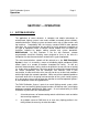
DMX Distribution System Page 3 Operation SECTION 1 -- OPERATION 1.1 SYSTEM OVERVIEW The application of recent advances in computer and robotic technologies to entertainment lighting systems have made available reasonably priced remotelycontrolled luminaires, dimming systems and accessories such as color scrollers and fog machines.
DMX Distribution System Page 4 Operation .3 A means of "patching" or “routing” a number of DMX control signals selectively to any or all lighting positions. .4 To accomplish the above while maintaining proper cabling practice and adhering to all relevant standards. To accommodate the above requirements, a typical theatre DMX Distribution System consists of the following major components: .
DMX Distribution System Operation 1.
DMX Distribution System Page 6 Operation In order to gain a full understanding of the how the DMX Distribution System is intended to be utilized, and, by extension, an appreciation of the advantages of this system, it is necessary to discuss briefly some concepts of data communications, how they have been applied to lighting control in general, and to this type of installation specifically. .1 Digital vs.
DMX Distribution System Page 7 Operation RS485, 100 ohms for RS422A). The main difference is that RS485 is capable of half-duplex transmission on the same wire pair, although this mode of operation is not compatible with the DMX Distribution System. .4 Communications Channel -- This is the path (sometimes called the data link or universe) over which the electronic signals travel from the transmitting device (i.e. the control console, also known as the data source) to the receiving device(s) (e.g.
DMX Distribution System Page 8 Operation on the communications channel. Each input signal always occupies the same frame position in the serial data stream. .6 Channel Transmission Modes -- A communications channel may operate in a simplex, half-duplex or full-duplex mode. In simplex mode, transmissions are in the same direction at all times. Half-duplex describes a transmission that may be in either direction, but only in one direction at a given moment of time.
DMX Distribution System Page 9 Operation systems since the early 1980s. Included are Avab A-240, Colortran CMX (also called D192 and C-156), Electro Controls EC-Mux, and Kliegl K96 and K100. All of these are compatible with the DMX Distribution System, since they are designed to work with RS-422A or RS-485 systems. In addition, manufacturers of automated lights have developed their own control protocols (sometimes called native protocols) that are for the most part compatible with the system.
DMX Distribution System Page 10 Operation (daisy-chain) topology to avoid the troublesome effects of signal reflection caused by a star wiring configuration. .11 Line Loading -- The star wiring configuration described above would also be prone to excessive loading of the data line with too many DMX receivers. Recall that an RS485 line driver is capable (under ideal conditions) of supporting up to 32 receivers. .
DMX Distribution System Page 11 Operation described, all of these channels include a separate circuit for communications in the reverse direction. All data channels are fully opto-isolated from the input signal and each other. Figure 1-2 on the next page shows a simple 1-in, 4-out opto-repeater application. There is one other important issue to be dealt with: .
DMX Distribution System Operation Figure 1-2: Simple 1-in 4-out Opto-Repeater Application Page 12
DMX Distribution System Operation Figure 1-3: Simple DMX Network with Terminators 1.
DMX Distribution System Page 14 Operation Proper use of the DMX Distribution System involves the electronic routing, or patching, of one or more source DMX signal lines to one or more output (receiving) stations, via the input and output modules in the distribution rack (DMXPathfinder). This technique eliminates the possibility of accidentally creating a "star" wiring configuration in the DMX Distribution System, as described in 1.2.10.
DMX Distribution System Page 15 Operation Remember that end-of-line termination is necessary on all individual DMX cable runs. Source lines are all permanently terminated by integral resistors in each Input Module, and likewise the auxiliary (return) wire pair of each outgoing station line is terminated in each Output Module. The transmit (send) wire pair of each station line, however, must be manually terminated at its final destination receiving device.
DMX Distribution System Page 16 Operation unpatched in the DMX-Q patch file, and the Input Module's channel must not have any other connected equipment. Better still, try to use an input channel permanently designated as "spare". It may be necessary for the system to output a DMX signal to receiving equipment located near the DMXPathfinder rack.
DMX Distribution System Page 17 Operation Figure 1-4: Output Frame Showing Locations of Connectors and Indicators
DMX Distribution System Page 18 Operation 1.4 BI-DIRECTIONAL SYSTEMS The DMX Distribution System has been designed to be compatible with certain receiving equipment that uses the second (auxiliary) wire pair to transmit return data back to the control system.
DMX Distribution System Page 19 Operation 1.5 BASIC TROUBLESHOOTING Basic fault-finding at the system user level is usually confined to observing the state of LED indicators on the face of the DMXPathfinder modules (refer to Figures 1.51.8). These can be scanned quickly to determine whether any problems exist.
DMX Distribution System Page 20 Operation .1 Module Replacement Should a defective Output Module or other module be found during troubleshooting, it is best to replace the module with a spare unit. Powering down the DMXPathfinder or at least the specific frame is recommended before removing or inserting modules. To replace a module, loosen its four captive Phillips screws, grasp the top and bottom handles, and pull the module straight out of the frame.
DMX Distribution System Operation Figure 1-5 Page 21
DMX Distribution System Operation Figure 1-6 Page 22
DMX Distribution System Operation Figure 1-7 Page 23
DMX Distribution System Operation Figure 1-8 Page 24
DMX Distribution System Page 25 Maintenance and Testing SECTION 2 -- MAINTENANCE AND TESTING 2.1 PREVENTIVE MAINTENANCE The DMXPathfinder will require a minimal amount of ongoing preventive maintenance to ensure a long, trouble-free life for the equipment. Maintenance will consist primarily of periodic cleaning and inspection of the distribution rack. .1 Cleaning Rack cleaning should be carried out once per year. Using compressed air at no higher than 100 p.s.i.
DMX Distribution System Page 26 Maintenance and Testing System testing by maintenance personnel will usually be carried out in response to a fault that has developed somewhere in the system. Powerful diagnostic instruments are available to assist the maintenance technician with his task: the Fluke Model 650 LAN CableMeter, and Goddard Design Li'l DMX'ter. These will be described in more detail below. In general, though, the procedures outlined in 1.5 Basic Troubleshooting and 2.
DMX Distribution System Page 27 Maintenance and Testing instrument will test cable continuity on all five XLR pins. Please refer to the Li'l DMX'ter Operating Manual for more information. .3 Other Test Equipment -- The maintenance technician will find the following additional test equipment useful: .
DMX Distribution System Page 28 Maintenance and Testing 2.3 ADVANCED TROUBLESHOOTING As described earlier, basic troubleshooting usually involves isolating a troublesome or defective opto-repeater circuit or module and replacing it with a known good module instead. It may also include checking for obvious things such as incorrect addressing on DMX receiving devices, absence of a line terminator, defective DMX patch cables, or even incorrect control console configuration.
DMX Distribution System Page 29 Maintenance and Testing suspect cable runs. This test will quickly indicate any anomalies having to do with cable impedance and capacitance that would result in excessive signal distortion or attenuation. This test will help to locate less-obvious problems such as pinched or over-heated cabling. .1 Diagnostics -- Chapter 5 in the DMX-Q Users Guide (Section 4 of this manual) covers the diagnostic features of the DMX-Q software.
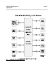
DMX Distribution System Page 30 DMXPathfinder - Hardware SECTION 3 -- DMXPathfinder HARDWARE 3.1 THEORY OF OPERATION Please refer to the Schematic Diagrams in Section 3.3 for assistance in following this discussion. The first schematic diagram, DMS SYSTEM SIGNAL FLOW, and Figure 3-1 on the following page, will be the subject of the initial discussion. The signal flow diagram shows the four main modular components of the Digital Matrix Switcher, or DMXPathfinder.
DMX Distribution System Page 31 DMXPathfinder - Hardware possible DMX signals on the I/O bus will be routed first to another opto-isolator, and then to the station line driver. Figure 3-1: Simplified DMXPathfinder Signal Flow (Example CBC Toronto Studio 42) 3.
DMX Distribution System Page 32 DMXPathfinder - Hardware .1 MASTER CONTROL MODULE -- DMS-MCM The main functions of the Master Control Module are to provide a communications link with a separate personal computer, provide local memory storage for patch information and the means for downloading it to the Input/Output Modules, and to monitor for system activity and status. It also acts as a buffer for system I/O data between the Input Modules and the system I/O bus.
DMX Distribution System Page 33 DMXPathfinder - Hardware repeat a hardware reset from the pushbutton to the Input Modules and the other frames respectively. JP1 is a test jig port for factory use only. PC COM Section (Sheet 1) -- UART U26 is used for controlling the PC COM ports. Three physical ports are provided, one on the front panel of the Master Module (J4) for a local portable PC using RS232C, and two on the master frame backplane via J1 for a remote hardwired PC using RS232C or RS422/485.
DMX Distribution System Page 34 DMXPathfinder - Hardware .2 FRAME CONTROL MODULE -- DMS-FCM The main function of the Frame Control Module is to act as a buffer for system I/O data between the Output Modules and the system I/O bus. It also monitors system I/O bus activity.
DMX Distribution System Page 35 DMXPathfinder - Hardware connected to the backplane via J1 to be used for active terminators on the Frame Bus. .3 INPUT MODULE -- DMS-IPM There are one to eight Input Modules in the DMXPathfinder Master/Input Frame.
DMX Distribution System Page 36 DMXPathfinder - Hardware provided for every connection. Relay status is returned to the microprocessor by an extra pole of K6. The external field wiring network is accessed via backplane connector J2, and front panel auxiliary connector J5 allows temporary insertion of input signals or monitoring with a DMX analyzer. L5-L8 are ferrite beads to suppress RFI/EMI emissions from cables plugged into the auxiliary connector.
DMX Distribution System Page 37 DMXPathfinder - Hardware the exception of "RUN" are controlled by the microprocessor. The RUN LED is driven from the watchdog timer. Crosspoint Matrix Section (Sheet 2) -- Two 16 x 4 crosspoint matrix devices are provided. U14 is the matrix device for data moving in the transmit direction through the system, and U11 handles data in the return direction. U11's four channels of input data are derived from the card's data I/O section.
DMX Distribution System Page 38 DMXPathfinder - Hardware module's four data I/O subsections. Optocouplers U27, U31, U35 and U39 are used to allow the card's microprocessor to monitor for power supply failure. .5 MODULE FRAMES -- DMS-132MF & DMS-132SF Please refer to the project shopdrawings in Section 5 for pictorial information. In most systems the first card frame is the Master/Input Frame, so named because it contains the Master Control Module and all Input Modules.
DMX Distribution System Page 39 DMXPathfinder - Hardware .6 SYSTEM COM BUS and I/O BUS In multi-frame systems, there are two sets of 40-conductor twisted-pair ribbon cables linking all of the frames. The system COM bus and system I/O bus run on these cables.