
Manual
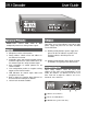


DMXDecoder User Guide
DMXDecoders convert DMX, AMX or D54
multiplexed protocols to analog control signals.
Operational Philosophy
Features
Indicators
• Microprocessor-based electronics
• Rotary address switch selects unit address in
one-dimmer increments
• Selectable status quo memory retention feature
maintains output levels at last known values for
five minutes upon loss of input control signal
• Auto recognition of control protocol on 24
channel models
• User-configuration positive or negative analog
outputs on 48 channel models
• LED indicators for control signal detect and
microprocessor status.
• Built in output test function allows dimmers to
be turned on from front panel switches
• 19 inch rack mount kit available
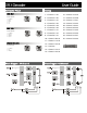
Address Selection
Three rotary switches select the offset start
address for the unit in most configurations. In test
mode, the switches set dimmers to full one at a
time. From left to right the switches are set as
hundreds, tens, and ones.
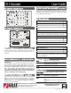
Two LEDs are used to indicate, from left to right,
power supply and processor run status and data
receive detection.
L1 : Glowing solidly indicates power supply and
processor OK; off indicates no power, and
flashing indicates defective processor
hardware.
L2 : Glowing solidly indicates data signal received;
off indicates no signal present. Note that an
Ad d re ss se le c t switc he s
Mo d e se le c t DIP switc he s
LED indic ators ( power and data )
1
2
3
4321
1
2
3
4
5
6
7
8
9
0
1
2
3
4
5
6
7
8
9
0
1
2
3
4
5
6
7
8
9
0
1
2
3