User’s Guide DMX Repeater Pro Version 3.0 January 2008 For Firmware Versions 1.4.0 and higher Suite 103, 1439 - 17 Avenue S.E. Calgary, AB, T2G 1J9 Canada Phone: Fax: (403) 243-8110 (403) 287-1281 E-mail: support@pathwayconnect.com www.pathwayconnect.
User’s Guide DMX Repeater Pro TABLE OF CONTENTS Overview .....................................................................................................................3 Protocols Supported ..................................................................................................4 Startup Displays .........................................................................................................4 Setting Basic Personalities ..............................................................
User’s Guide DMX Repeater Pro OVERVIEW This manual describes the function and configuration options for the Pathway Connectivity DMX Repeater Pro with firmware versions of 1.4.0 or higher. Some features and menu choices described below are not found in earlier firmware. Firmware is not currently upgradeable by the end user. The DMX512 entertainment lighting control protocol is accepted throughout the world as the standard for interoperability between equipment supplied by most manufacturers.
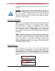
User’s Guide DMX Repeater Pro as an RDM device, as well as providing the functions of an in-line controller. Warning: Except for the IEC chassis plug marked for AC input, all ports on the DMX Repeater Pro are intended for low voltage data lines only. The 250 volt fault protection is not intended as primary personal protection. Attaching anything other than low voltage sources to the data ports may result in severe equipment damage, and personal injury or death.
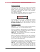
User’s Guide DMX Repeater Pro DMX Status: The first display shows DMX activity and the number of current input channels detected. Some controllers transmit less than a full universe of 512. If there is no DMX present, the display will read ‘DMX Input – Inactive’. RDM Status: The second display shows RDM activity and the number of RDM messages since power was last cycled on the Repeater Pro. In some modes, the screen will read “RDM Disabled”.
User’s Guide DMX Repeater Pro Selecting a Personality To begin, press the Home button. The screen will read “Pathway DMX Repeater Pro” and the OK button will light up green. Press the up/down arrows to cycle through the following screens: “Discover RDM Devices”, “DMX Monitor and Console”, “Status Information” and “Repeater Configuration”. When “Repeater Configuration” appears, press the check-mark to select.
User’s Guide DMX Repeater Pro to them. If DMX signal is lost, the Repeater Pro will begin the scanning process all over again. This personality allows one console to be moved easily between multiple input locations without use of extension cables or patch bays, or alternately to allow a back-up to rapidly take over from a failing primary console. In DMX Hub mode, active signal appearing at the “DMX IN” port will take immediate priority over any other active signal. Also see “More on DMX Hub Mode”.
User’s Guide DMX Repeater Pro LCD Backlight. Use the up\down arrows to set the desired level of backlight and the check-mark to accept. The factory setting is full. The backlight does not dim itself after a period of idleness. PORT CUSTOMIZATION OPTIONS While setting the personality and global parameters, you will have scrolled past several screens that look like this: ▲Port x Source ▼Input (RDM) ▲ ▼ where x is a letter between A and H, referring to a DMX/RDM port on the DMX Repeater Pro.
User’s Guide DMX Repeater Pro In DMX Hub mode, selecting a port forces the DMX Repeater Pro to switch signal sources, but only if DMX is active at the new port and it has a higher letter (e.g. C is higher than D). For example, the primary console is plugged into Port A, but has crashed. The DMX Repeater Pro has automatically switched to the back-up console in Port B.
User’s Guide DMX Repeater Pro The Console function sends a DMX level to all output ports, allowing an independent check on downstream or end devices. Use the left/right arrows to highlight the desired channel on the display and press the check mark to select it. The level information on the right hand side will blink. Use the up/down arrows to change the channel’s level. Check if the end device is reacting accordingly.
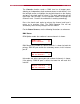
User’s Guide DMX Repeater Pro Port Status: The letters appearing below the Port indicate the port’s customization. Many combinations are possible; the examples are generic for clarity. ▲Port ABCDEFGH▲ ▼Src IIIIIIII▼ The letter “I”: Indicates the port is sourced from the primary input “DMX IN” and that RDM is enabled. ▲Port ABCDEFGH▲ ▼Src CCCCCCCC▼ Letters “A” through “H”: Indicates the port is in Hub mode and is sourcing its signal from the indicated port.
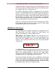
User’s Guide DMX Repeater Pro RDM DISCOVERY The DMX Repeater Pro provides a straight-forward interface to discover and configure RDM-enabled devices. From the “Pathway DMX Repeater Pro” screen, press the down arrow until the screen reads “Discover RDM Devices”. Press the check mark and the screen should read “Use arrows to discover.” If a discovery has previously been done, the screen will go directly to showing device UIDs (Unique Identifiers). Pressing the up or down arrow starts discovery.
User’s Guide DMX Repeater Pro MORE ON DMX HUB MODE When hard-wiring a number of console input receptacles to a dimming or distribution system, the usual practice would be to daisy chain them to the dimmer rack or opto-splitter. While this method often works with no apparent problems, this practice is expressly forbidden by DMX rules. The problem has been that there is no realistic ‘legal’ alternative. The DMX Repeater Pro remedies this.
User’s Guide DMX Repeater Pro MORE ON DMX MERGER MODE Often an installation requires an architectural controller and a lighting console to be active on the same DMX universe or even to simultaneously access different dimmers within the same rack. Although resolvable with a merger card, the situation can become hopelessly complicated if the secondary source must move between numerous locations.
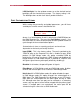
User’s Guide DMX Repeater Pro APPENDIX A – XLR CONNECTOR PINOUTS DMX512A 1 – Common 2 – Data – 3 – Data + 4 – Data 2 – (not used) 5 – Data 2 + (not used) PUSH 5 4 3 1 1 2 2 OUT (F) 5 4 3 IN (M) Note: Although unused under DMX512, pins 4 and 5 are connected on the DMX Repeater Pro, which should be taken into consideration in systems including manufacturers’ proprietary signals on pins 4 and 5.