Instruction Manual Manual No. 012-05804C Force Sensor Model No.
Force Sensor Model No. CI-6537 Table of Contents Equipment List........................................................... 3 Introduction ............................................................. 4 Equipment Setup ..................................................... 5-6 Mounting the Force Sensor on a PASCO Dynamics Cart .............................................................5 Mounting the Force Sensor on a Support Rod .............................................................................
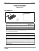
Model No. CI-6537 Force Sensor Force Sensor Model No. CI-6537 Equipment List 3 1 CA UT IO N! +5 0N -50 N SEFOR NS CE OR 2 Included Equipment 1. Force Sensor (1) 2. Hook and bumper (2) 3. Ziplock bag (1) Replacement Model Number* CI-6537 003-05798 NA *Use Replacement Model Numbers to expedite replacement orders.
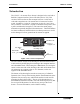
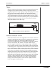
Force Sensor Model No. CI-6537 Introduction Use No.0 Phillips head screw driver to attach to PASCO Dynamics Cart Output: ± 8V for ± 50 N CI-6537 (Button on side) Thumbscrew Hole for support rod Threaded hole mounting screw Tare button T AR E Detachable hook FORCE SENSOR + 50 N Push To Tare CAUTION! Do Not Exceed 50 Newtons. (Push or Pull) 50 N The CI-6537 ± 50 newton Force Sensor is designed to be used with a PASCO Computer interface [ScienceWorkshop 500 or 750].
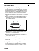
Model No. CI-6537 Force Sensor Equipment Setup Mounting the Force Sensor on a PASCO Dynamics Cart The Force Sensor has two built-in mounting screws that align with the threaded holes in the accessory tray of a PASCO Dynamics Cart (such as the ME-9430 Plunger Cart or ME-9454 Collision Cart). The screws are spring loaded so they remain in a retracted position when not in use. 1. Position the sensor lengthwise it in the accessory tray of the Dynamics Cart. 2.
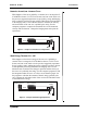
Force Sensor Model No. CI-6537 Mounting the Force Sensor on the IDS Force Sensor Bracket The Force Sensor can be mounted on the CI-6545 Force Sensor Bracket. 1. Place the bracket on top of the sensor so the thumbscrews align with the threaded holes in the top of the sensor accessory tray. 2. Turn each thumbscrew clockwise until it is tight. 3. Mount the Force Sensor Bracket on the T-slot on the side of the IDS Track. For more information, see the Force Sensor Bracket instruction sheet.
Model No. CI-6537 Force Sensor -1.60 volts equals a force of -10 newtons (in other words, a pull of 10 newtons). If you want to calibrate for greater accuracy, follow the instructions in Appendix C. Using the Force Sensor with PASCO Interfaces The instructions in this manual are intended for those using the Force Sensor with the PASCO 500 or 750 ScienceWorkshop interfaces. Using the Force Sensor with older PASCO interfaces may require additional instructions.
Force Sensor Model No. CI-6537 Suggested Experiments Component of Force on an Incline Plane When a cart is at rest on an inclined plane, the component of force acting on the cart that is parallel to the plane is mgsinθ, where mg is the weight of the cart and θ is the angle of the plane. Use the sensor to measure the weight of a dynamics cart. Mount the sensor at the high end of the inclined IDS track and connect it with a string to the dynamics cart on the track. Measure the angle of the track.
Model No. CI-6537 Force Sensor Newton’s Second Law: Constant Force What happens if the cart is pulled by a constant force? Arrange the CI6742 Motion Sensor, CI-6537 Force Sensor, and cart on the track as in the previous suggested experiment. Set up a pulley, string, and hanging mass so that the cart/Force Sensor will be pulled by the string attached to the hanging mass. Use the Motion Sensor to measure the velocity and acceleration of the cart as it is pulled by the string.
Force Sensor Model No. CI-6537 Tension What is the tension in the string in the previous suggested experiment? Arrange the Force Sensor and cart on the track as in the previous suggested experiment. Set up a pulley, string, and hanging mass so that the cart/Force Sensor will be pulled by the string attached to the hanging mass. First, hold the cart at rest so the tension in the string is “mg” (the hanging mass times the acceleration due to gravity).
Model No. CI-6537 Force Sensor Motion Sensor Force Sensor Pulley Cart Friction Pad Mass Figure 8: Setup for Friction Experiment Newton’s Third Law “For every action, there is an opposite but equal reaction.” Whenever one object exerts a force on a second object, the second object exerts an equal and opposite force on the first. Use two force sensors. Set up the computer program so that a push will be negative for one of the sensors.
Force Sensor Model No. CI-6537 Other Suggested Experiments • Measure the force of a fan cart. • Measure the centripetal force of a swinging pendulum, and compare the force to the speed, length, and mass of the pendulum. • Measure the change in mass of liquid nitrogen as it vaporizes versus the energy input to vaporize the liquid nitrogen. • Measure fluid drag forces on objects of various shapes in a wind tunnel. • Measure the net force acting on a pair of harmonic oscillators.
Model No. CI-6537 Force Sensor Appendix A: Specifications Force Sensor: Output voltage +8 V for +50 newtons (pushing) + 8 V for -50 newtons (pulling) Output noise +/- 2 millivolts Slew Rate 25 newtons/millisecond Range* +/- 50 newtons Resolution** 0.0305 newtons (or 3.1 grams) Bandwidth limit 2 kilohertz (internal low pass filter) Output drive 8 meters of cable without instability * The range of the sensor is +/- 50 newtons with an output between -8 to +8 volts, or 160 millivolts per newton.
Force Sensor Model No. CI-6537 Appendix B: Calibration using DataStudio Software All calibrations assume that the sensor produces an output voltage that is linear with respect to the input signal. Calibration is done by setting up two calibration situations (such as “no force” and a known force), measuring the input signal in each situation in comparison to a known standard, and entering the readings. Whenever possible, calibrate the Force Sensor in the orientation in which it will be used.
Model No. CI-6537 Force Sensor Calibration Procedure (for Long-Term Measurements) When you plan to measure force over long periods, you must allow time for the aluminum beam to relax in your calibration; otherwise your experimental results may contain error. The mass of the beam is approximately 37 g. 1. Tare the force sensor where you wish to define zero. 2. Apply the typical force that will be encountered during the experiment. 3. Wait 2-4 minutes for the aluminum beam to relax.
Force Sensor Model No. CI-6537 Appendix C: Calibration using ScienceWorkshop ® Software You will need a known mass, such as 1 kilogram, and a support rod for mounting the sensor. a) Connect the Force Sensor to the ScienceWorkshop® interface. When the Science Workshop program begins, click-and-drag the analog sensor plug icon to analog Channel A on the interface. b) Select “Force Sensor” from the list of analog sensors.
Model No. CI-6537 Force Sensor Appendix D: Technical Support For assistance with the CI-6537 Force Sensor or any other PASCO products, contact PASCO as follows: Address: PASCO scientific 10101 Foothills Blvd. Roseville, CA 95747-7100 Phone: (916) 786-3800 FAX: (916) 786-3292 Web: www.pasco.com Email: techsupp@pasco.
Force Sensor Model No. CI-6537 Appendix E: Copyright and Warranty Information Copyright Notice The PASCO 012-05804B Force Sensor Manual is copyrighted and all rights reserved. However, permission is granted to non-profit educational institutions for reproduction, of any part of the 012-05804B Force Sensor Manual, providing the reproductions are used only for their laboratories and are not sold for profit.