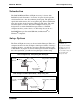
Instruction Manual Manual No. 012-05088D Time of Flight Accessory Model No. ME-6810 RY RANGE HER SHORT LAUNC CTILE CAUTION! LOOK DO NOT BARREL! DOWN PROJE -O E TIM L UT NA TP SIG +5V OU GND L ITA DIG ME-6800 H IG L F-F E CC TA WEAR SAFETY GLASSES IN USE.
Time of Flight Accessory Model No. ME-6810 Table of Contents Equipment List........................................................... 3 Equipment Requirements for Suggested Experiments...................................................................4 Introduction ............................................................. 5 Setup Options ........................................................... 5 Set up the Time of Flight Accessory with a Photogate Timer ...........................................
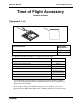
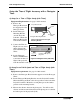
Model No. ME-6810 Time of Flight Accessory Time of Flight Accessory Model No. ME-6810 Equipment List 1 2 Y OR SS 10 CE C -68 ME HT A RANGE SHORT LAUNCHER WEAR SAFETY GLASSES IN USE. WHEN ME-6800 CAUTION! LOOK DO NOT BARREL! DOWN ITAL DIG L UT NA TP SIG +5V OU GND PROJECTILE -F OF E- TIM LIG TION Y! CAU PLASTIC USEBALLS ONL Included Equipment Replacement Model Number* 1. Time of Flight Accessory ME-6810 2.
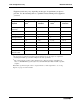
Time of Flight Accessory Model No. ME-6810 Equipment needs may vary, depending on the types of experiments you plan to perform. Use the following table as a guideline for determining what equipment you need.
Model No. ME-6810 Time of Flight Accessory Introduction The PASCO ME-6810 Time-of-Flight Accessory is for use with PASCO Projectile Launchers. It consists of a piezo-electric speaker circuit mounted on a 20 x 20 centimeter plastic plate. The plate has a signal cable with a 6 mm (1/4”) stereo phone plug. When a ball hits the plate, the speaker circuit generates a Photogate-like pulse. The cable sends the signal to a timer.
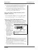
Time of Flight Accessory Model No. ME-6810 Setup the Time of Flight Accessory with a Photogate Timer a) Setup for a Time of Flight Study (with Timer) Equipment Requirements: See page 4 of this manual. 1. Remove the Photogate Head from the support rod of the Photogate Timer. 2. Put the Photogate Mounting Bracket onto the Projectile Launcher. Mount the Photogate Head at the front of the Launcher.
Model No. ME-6810 Time of Flight Accessory 4. Connect the stereo plug of the first photogate into the Timer. Set the Photogate Timer to PULSE mode to measure the time of the projectile from the first photogate to the second photogate. 5. Connect the stereo plug of the Time of Flight Accessory into a second timer or a Smart Timer (ME-8930). (Note: If you do not wish to measure time of flight, skip this step.
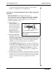
Time of Flight Accessory Model No. ME-6810 pad. (For information about using computer software with the interface, see Appendices A-C of this manual). b) Set up for an Initial Speed and Time of Flight Study (with interface) Equipment Required: 2 Photogates with brackets, 1 ScienceWorkshop® interface (CI-6400 or CI-6450) OR 2 PASPORT Photogate Port (PS-2123) with 2 USB Links (PS-2100) and USBcompatible computer, 1 Time of Flight Accessory, 1 Projectile Launcher, DataStudio software 1.
Model No. ME-6810 Time of Flight Accessory Experiment 1: The Relationship between Time of Flight and Initial Velocity Equipment required Computer interface (CI-6450 or CI-7599 or PS-2123 with PS-2100)* Projectile Launcher and ball (ME-6800 or ME-6801) Time-of-Flight Accessory (ME-6810) Photogate Mounting Bracket (ME-6821) Phone Jack Extender Cable (PI-8117) Photogate Head (ME-9498) *If a computer interface is not available, use a Photogate Timer (ME-8930).
Time of Flight Accessory Model No. ME-6810 4. Connect the Time-of-Flight Accessory into the computer interface using the extender cable. 5. Run the timing program and set it to measure the time between the blocking of two photogates (one Photogate and the timer plate of the Time-of-Flight Accessory). Procedure: 1. Put the plastic ball into the Projectile Launcher and cock it to the short range position. 2. Test fire the ball to determine where to place the timer plate on the floor.
Model No.
Time of Flight Accessory Model No. ME-6810 4. Connect the Time-of-Flight Accessory to the computer interface using the extender cable. 5. Run the timing program and set it to measure the time between the three successive signals (two Photogates and the timer plate of the Time-of-Flight Accessory). Procedure: 1. Put the plastic ball into the Projectile Launcher and cock it. 2. Test fire the ball to determine where to place the timer plate on the floor. Put the timer plate on the floor where the ball hit.
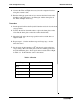
Model No. ME-6810 Time of Flight Accessory Results Angle_________________ Time between photogates___________ Time between second photogate and timer plate______________ Distance to paper_____________________ Table 2.1: Results Distance 1 2 3 4 5 6 7 8 9 10 Average Table 2.
Time of Flight Accessory Model No.
Model No. ME-6810 Time of Flight Accessory bracket. Plug the Photogate into Channel 1 on the computer interface. 4. Connect the Time-of-Flight Accessory to the computer interface. Use the extender cable if necessary. 5. Run the timing program and set it to measure the time between blocking of two Photogates (one Photogate and the timer plate of the Time-of-Flight Accessory). 6. Set up the vertical target board about 0.5 m in front of the Projectile Launcher.
Time of Flight Accessory Model No. ME-6810 Teacher’s Guide Experiment 1: The Relationship between Time of Flight and Initial Velocity Notes on Setup: 2. It is important to keep the launcher exactly horizontal. Use a spirit level for best results. 3, 4. You may use one of several timing options for this experiment. Consult the manual for your computer interface, and then connect things so that the Photogate starts the timer and the timer plate of the Time-of-Flight Accessory stops it.
Model No. ME-6810 Time of Flight Accessory 4. The initial velocity should be close to that measured in other experiments (See manual experiments 1 and 2, for example.) 6. The difference should be less than 5%. Experiment 3: Horizontal Velocity of a Projectile Notes on Setup: 3-5. If necessary, consult your interface manual. The system should be set up in such a way that the computer measures the time between the Photogate and the timer plate. 6.
Time of Flight Accessory Model No. ME-6810 Appendix A: DataStudio Software Instructions for Using the Time of Flight Accessory with a PASPORT Interface Instructions for an Initial Velocity and/or Time of Flight Study 1. Connect the photogate and time of flight accessory stereo plugs to the Photogate Ports. [Note: You will need 1-2 photogates and 1-2 PASPORT Photogate Ports (PS-2123). See the PASPORT interface Note: To change measetup instructions on page 7 of this manual.] 2.
Model No. ME-6810 Time of Flight Accessory Appendix B: DataStudio Software Instructions for Using the Time of Flight Accessory with a ScienceWorkshop Interface Instructions for an Initial Velocity and/or Time of Flight Study 1. For a time of flight study: Connect the stereo phone plug of the photogate to digital channel 1 on the ScienceWorkshop interface and the Time-of-Flight Accessory plug into digital channel 2.
Time of Flight Accessory Model No. ME-6810 blocked. b) In the Timing Sequence menu for channel 2, click on the down arrow and select “On” to record the time that the ball hits the time-of-flight pad. c) To accept your timing sequence, click the Done button. An icon for the timed entry will appear in the Data List. 11. For an initial speed and time of flight study: You will need to create two timers for this experiment: one timer for “Time between Gates” and a second timer for “Time of Flight”).
Model No. ME-6810 Time of Flight Accessory Appendix C: ScienceWorkshop Software Instructions for Using the Time of Flight Accessory with a Computer Interface a) Time of flight Study (Macintosh or Windows) 1. Perform equipment setup instructions on pages 5-6 of this manual. 2. Connect the photogate’s stereo phone plug into digital channel 1 on the interface. 3. Connect the Time of Flight Accessory stereo phone plug into digital channel 2 on the interface. 4. Start the ScienceWorkshop program.
Time of Flight Accessory Model No. ME-6810 “Display” to return to the Experiment Setup window. The Table display will show “vInitial (m/sec)” and “tFlight(sec).” You are ready to begin collecting data.
Model No. ME-6810 Time of Flight Accessory Appendix D: Technical Support For assistance with the ME-6810 Time of Flight Accessory or any other PASCO products, contact PASCO as follows: Address: PASCO scientific 10101 Foothills Blvd. Roseville, CA 95747-7100 Phone: (916) 786-3800 FAX: (916) 786-3292 Web: www.pasco.com Email: techsupp@pasco.
Time of Flight Accessory Model No. ME-6810 Appendix E: Copyright, Warranty, and Equipment Return Copyright Information The 012-05088D Time of Flight Accessory Manual is copyrighted and all rights reserved. However, permission is granted to non-profit educational institutions for reproduction of any part of the Time of Flight Accessory Manual, providing the reproductions are used only for their laboratories and are not sold for profit.