Instruction Ma nual 012-13762D Materials Testing Machine ME-8236 Part of the Comprehensive Materials Testing System ME-8244 WARNING: Provide proper eye protection when using the Materials Testing Machine or its Accessories. Operate the Materials Testing Machine behind protective Safety Shields.
M a t e r i a l s T e s t in g M a c h in e Introduction Materials Testing Machine (ME-8236) Table 2: Comprehensive Materials Testing System Model Comprehensive Materials Testing System Items ME-8230 Materials Testing System (MTS) ME-8229 Materials Testing System Base ME-8237 Materials Bending Accessory Required Items* ME-8238 Materials Coupon Adapter PASCO Interface (PASPORT compatible) ME-8239 Materials Shear Accessory PASCO Capstone Data Collection Software ME-8240 Materials Shear Samp
Model No.ME-8236 Materials Testing System Included Equipment The table shows typical values. Table 3: Typical Values The Materials Testing Machine (ME-8236) includes a calibration rod and nut, a load bar round nut, and a pair of safety shields with Velcro® hook material.
M a t e r i a l s T e s t in g M a c h in e Operation ME-8229 MTS Storage Base PASCO Capstone data collection software includes a “calibration wizard” that allows the calibration information called a “compliance calibration” - for the Materials Testing Machine to be stored for later use. (PASCO Capstone is provided in the ME-8230 Materials Testing System.
Model No.ME-8236 O p e r a ti o n Creating the Compliance Calibration Information In the software, a polynomial curve fit is applied to the plot of position versus force data. The coefficients of the polynomial curve fit are saved as the calibration information. Once the compliance calibration is created for the Machine, the software automatically subtracts the amount of “flex” from the raw data. After the calibration information is stored in the Machine, it cannot be edited.
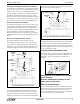
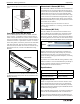
M a t e r i a l s T e s t in g M a c h in e Operation Lower the load bar so that the longer threaded section of the sample goes up through the hole in the center of the load bar. Adjust the load bar until the bottom edge of the longer threaded section is flush with the bottom of the load bar. While holding the tensile sample so it does not turn, screw the sample nut onto the longer threaded section until the sample is held tightly in place. bar using the sample nut.
Model No.ME-8236 O p e r a ti o n Hold the upper clamp so it remains parallel to the lower clamp and tighten the sample nut slightly to remove any slack in the coupon. Fixed Jaw Attach the Safety Shields Attach the Velcro® hook material on the two safety shields to the Velcro® loop material on the front and back of the Load Bar and adjust the position of the shields if needed. Movable Jaw Hex Nut Loosen but do not remove the hex nut on each clamp.
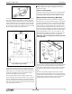
M a t e r i a l s T e s t in g M a c h in e Operation To place the polarizers on the Load Bar, align a polarizer with the strips of loop material on the front of the Load Bar and press the edges of the polarizer so that the hook material adheres to the loop material. Repeat the process with the second polarizer on the other side of the load bar. Materials Shear Accessory Figure: Materials Shear Accessory Adjust the position of the load bar so that it rests on the top surface of the front piece.
Model No.ME-8236 O p e r a ti o n Remember to attach the two safety shields to the Load Bar. MTS 10 – 32 Adapter (ME-8246) There are several devices used in material testing that hold materials in place and have a threaded 10 - 32 hole designed for mounting the device on a materials tester, such as the Materials Testing System. The Materials 10 - 32 Adapter is designed to connect devices with a threaded 10 - 32 hole to the Load Bar and Load Cell of the Materials Testing Machine.
M a t e r i a l s T e s t in g M a c h in e Operation ture of tested samples can be measured, recorded, and analyzed. Photoelastic I-Beams (ME-7011) The Photoelastic I-Beams are similar to the #3 I-Beams and #4 I-Beams that are part of the PASCO Structures Systems (such as the Truss Set, ME-6990). However, the Photoelastic I-Beams differ in that they are clear polycarbonate plastic and do not have any holes in the web area of the beam.
Model No.
Materials Testing Machine Appendix A: Calibration Appendix A: Calibration General Information: Pre-Calibration Lab 02: Compliance Calibration Tutorial REMINDER: A PASCO Capstone workbook file about compliance calibration is available to download from the PASCO web site. Go to www.pasco.com and enter “Materials Testing System” in the Search window. In the web page that opens, select Materials Testing System. Click “Sample Labs” and then download the ZIP file for Lab 02.
Model No.ME-8236 A p p e n d i x A : C a l i b r a ti o n Calibration Procedure The following steps describe how to use the “calibration wizard” in PASCO Capstone to create a compliance calibration for the Materials Testing Machine. Please preview the steps to become familiar with the procedure before doing the calibration. Step One: Choose the Type of Measurement to Calibrate In the Capstone software, select the “Calibration” icon ( Tools palette to open the “Calibration” window.
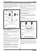
Materials Testing Machine Appendix A: Calibration • Import Calibration From Sensor: If any compliance calibrations have been stored in the Materials Testing Machine (the “Sensor”), they will be displayed in the pull down menu. (The stored calibration “7100N 100N pre (Tue Feb 25)” is shown as an example.) If you click Finish, the selected stored calibration will be imported and added to the list for use. It will also become the “active” calibration.
Model No.ME-8236 A p p e n d i x A : C a l i b r a ti o n Step Three: Install the Calibration Rod The ‘calibration wizard” changes to show an illustration about how to install the calibration rod. In addition to the illustration, a Graph display of Position (m) versus Force (N) opens. A Digits display of Force (N) is part of the Graph display. Position (m) Digits display of Force (N) Force (N) • Click Next to show Step Four: “Record a smooth data run”.
Materials Testing Machine Appendix A: Calibration Step Five: Polynomial Fit NOTE: By default, the “Show Curve Fit Editor” window is open in the “Polynomial Fit” window. The Curve Fit Editor window shows the default values for the coefficients of the polynomial. In the Curve Fit Editor window you can change the “Number of Terms”, enter an “Initial Guess” for each coefficient and lock or unlock a coefficient value.
Model No.ME-8236 • A p p e n d i x A : C a l i b r a ti o n From the “File” menu, save the Capstone file for future use.
Materials Testing Machine Appendix B: “Seating” a Test Sample and Setting a Pre-Load Appendix B: “Seating” a Test Sample and Setting a Pre-Load In the following procedure, a test sample is stretched and relaxed to properly “seat” the sample (remove any slack) and a pre-load is set. “Seat” the Sample 1. Mount a test sample onto the Materials Testing Machine. Make sure that the Load Bar Round Nut is slightly loose and not applying a force on the test sample. 2.