012-04346B Instruction Manual and Experiment Guide for the PASCO scientific Model PK-9023 05/91 EQUIPOTENTIAL AND FIELD MAPPER d l an nua for the l Ma l ona uide ode ucti ent G tific M tr s In perim scien Ex SCO PA -9023 PK LD FIE PER MAP l and Manua for the tional Guide Model fic Instruc ment Experi scienti PASCO23 PK-90 LD PER MAP FIE USA tific scien • Blvd. Foothills786-3800 10101 (916) Phone • 619011 Box P. O.
012-04346B Table of Contents Section Page Copyright, Warranty, and Equipment Return ................................................... ii Introduction ...................................................................................................... 1 Equipment ......................................................................................................... 1 Equipment Setup...............................................................................................
012-04346B Copyright and Warranty Please—Feel free to duplicate this manual subject to the copyright restrictions below. Copyright Notice The PASCO scientific Model PK-9023 Equipotential and Field Mapper manual is copyrighted and all rights reserved. However, permission is granted to non-profit educational institutions for reproduction of any part of this manual providing the reproductions are used only for their laboratories and are not sold for profit.
012-04346B Introduction The PASCO scientific MODEL PK-9023 Field Mapper consists of two basic elements. The first is a carbon impregnated paper in the resistance range of 5 KΩ to 20 KΩ per square. This paper forms the conducting medium or space between the electrodes. The second element is a conductive ink dispensed from a pen. The ink is produced from silver particles in a suspension liquid.
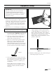
012-04346B Equipment Setup IMPORTANT: The silver conductive ink reaches its maximum conductivity after 20 minutes drying time. For optimal results plan the timetable for conducting the experiments and correlate drawing the conductive ink paths accordingly. 1. Plan and sketch the layout (size, shape and relative spacing) of the charged paths to be studied on a piece of scratch paper. These paths can be any two dimensional shape, such as straight or curved lines, circles, dots, squares, etc.
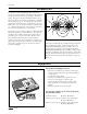
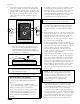
012-04346B 4. 5. Connect the electrodes to a battery, DC power supply, or any other potential source in the 5 to 20 VDC range using the supplied connecting wires. (see Figure 4) The potential source should be capable of supplying 25 mA. (If possible, the potential should be equal to the full scale reading of the electronic voltmeter used in the experiment.) To check the electrodes for proper conductivity connect one voltmeter lead near the push pin on an electrode.
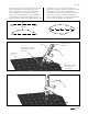
012-04346B arrow. Repeat the action of pivoting and touching with the front lead until the potential reading in a given direction is highest. Draw a new arrow. Repeat the action of putting the ground lead at the tip (head) of each new arrow and finding the direction in which the potential difference is highest. Eventually , the arrows drawn in this manner will form a field line. Return to the dipole and select a new point at which to place the voltmeter's ground lead.
012-04346B Experiments The following are only some suggested experiments in mapping equipotentials and field gradients using the PASCO Field Mapper. The true value of the equipment, lies in its complete flexibility permitting the user to design any system of charged bodies and then to map the equipotentials and field gradients. NOTE: Only power supply connections are shown in the following schematics.
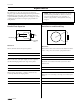
012-04346B Dipoles of Opposite Charge Dipoles of Like Charge + + Questions Questions What is the relation between the direction of a maximum value field gradient and equipotential line at the same point? (A geometrical relation is desired.) How does the field of this configuration compare with dipoles of opposite charge? (See experiment “Dipoles of Opposite Charge”.
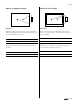
012-04346B Floating Insulator Floating Electrode Rectangular cut-out + + Before drawing the circular electrode, map the equipotentials of the two straight electrodes. Draw the circular electrode and again map the equipotentials. Before cutting the rectangular insulator, map the equipotentials of the two straight electrodes. Cut out a rectangular section of the paper and again map the equipotentials.
012-04346B Line and Circular Source Line and “Sharp” Point b a a + + a c At first, do not draw the two electrodes marked “a.” Map the equipotentials. Add the electrodes “a” and again map the equipotentials. Draw only the line and point source “a.” Map the equipotentials. Add circular electrode “b” and again map the equipotentials. Add circular electrode “c” and again map the equipotentials.
012-04346B Triode flow and electric fields. In particular, the velocity potential of an incompressible fluid where the flow is both steady and not rotational satisfies the Laplace equation. A steady flow of water is a good approximately of this type of flow. Now the flow is generated by “sources” which supply fluid and “sinks” which absorb fluid. We are interested in the “streamlines” which can be thought of as lines traced out by a particular particle in the fluid.
012-04346B Notes 10 scientific
012-04346B Appendix scientific 11
012-04346B 12 scientific
Technical Support Feedback Contacting Technical Support If you have any comments about the product or manual, please let us know. If you have any suggestions on alternate experiments or find a problem in the manual, please tell us. PASCO appreciates any customer feedback. Your input helps us evaluate and improve our product.