
User's Manual

2
Diode Laser for Optics Systems 012-11248A
®
DIODE LASE
0496
®
10101 Foothill B
lvd.
R
oseville, C
A
. 95747 U
S
A
RED DIO
DE LASE
R
003-10496
AVOID EXPOSURE
LASER LIGHT IS EMITTED
FROM THIS APERTURE
®
O
S
-8
5
2
8
A
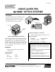
DIODE LASER FOR
OPTICS SYSTEMS
1
0
1
0
1
F
o
o
th
ill B
lv
d
.
R
o
s
e
v
ille
, C
A
9
5
7
4
7
U
S
A
Manufactured by:
®
9 VDC 500mA
GND
3.5mm
HORIZONTAL
ADJUST
VERTICAL
ADJUST
O
N
O
F
F
POWER
+9VDC
OS-8528A
D
IO
D
E
L
A
S
E
R
F
O
R
O
P
T
IC
S
S
Y
S
T
E
M
S
10101 Foothill Blvd.
Roseville, CA 95747 USA
M
a
n
u
fa
c
tu
r
e
d
b
y
:
®
R
E
D
D
IO
D
E
L
A
S
E
R
0
0
3
-
1
0
4
9
6
A
V
O
I
D
E
X
P
O
S
U
R
E
L
A
S
E
R
L
I
G
H
T
I
S
E
M
I
T
T
E
D
F
R
O
M
T
H
I
S
A
P
E
R
T
U
R
E
®
Assembly
➀
Determine the configuration of your experiment
and the location in which the Diode Laser will be
set up and adjust the orientation of the Diode Laser
accordingly. Make sure the face of the laser diode
assembly is relatively perpendicular to the surface
of your optics bench. This will minimize the
amount of fine adjustment you may need to per-
form in step 4. Tighten the thumbscrew to secure
the laser diode module.
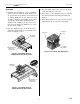
➁ Place the “alignment edge” of the Diode Laser
against the alignment rail of your PASCO optics
bench. See Figures 2 and 3.
Figure 2: Laser Diode Setup for
PASCO Introductory Optics bench
PASCO Advanced
Optics bench
(not included)
Figure 3: Laser Diode Setup for
PASCO Advanced Optics bench
OS-8528A
Laser Diode
PASCO Introductory
Optics bench
(not included)
OS-8528A
Laser Diode
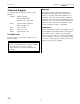
➂ Plug the 9VDC adapter phone plug into the back
of the laser and turn on the laser.
➃ If necessary, use the adjustment screws to align the
laser beam from left-to-right and up-and down. See
Figure 4.
➄ When using with the Laser Slits, OS-8529, slide the
Laser Diode to the top of the slots on the mount.
Figure 4: Laser Beam Fine Adjustment
input jack
(9VDC)
adjustment
screws
mount slots
Mfg I.D.
Label