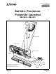
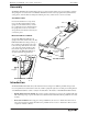
Instruction Manual 012-05375C ® *012-05375* Ballistic Pendulum/ Projectile Launcher ME-6830, ME-6831 Angle indicator Vertical upright Trigger String Ballistic Pendulum Projectile Launcher Base Included: Ramrod, 2-D Collision Accessory, Steel Balls (2), Plastic Balls (3) Not shown: Safety Glasses (2 pair)
The cover page shows the PASCO Ballistic Pendulum with the Short Range Projectile Launcher mounted on the vertical part of the base. The Ballistic Pendulum is designed for traditional ballistic pendulum experiments and can also be used for projectile motion experiments and demonstrations. When the Projectile Launcher is used for projectile motion experiments, the launch angle at the upper launch position can vary from 0 to 90 degrees, and the firing height is fixed for any launch angle.
Table of Contents Equipment . . . . . . . . . . . . . . . . . . . . . . . . . . . . . . . . . . . . . . . . . . . . . . . . . . . . . . . . . . . . 1 Assembly . . . . . . . . . . . . . . . . . . . . . . . . . . . . . . . . . . . . . . . . . . . . . . . . . . . . . . . . . . . . . 2 Introduction . . . . . . . . . . . . . . . . . . . . . . . . . . . . . . . . . . . . . . . . . . . . . . . . . . . . . . . . . . . 2 General Operation of the Projectile Launcher . . . . . . . . . . . . . . . . . . . . . . . . .
Projectile Launcher iv 012-05375C ®
Ballistic Pendulum / Projectile Launcher ME-6830, ME-6831 Equipment The ME-6830 Ballistic Pendulum / Projectile Launcher includes the following: Included Equipment Part Number Ballistic Pendulum and Base (unassembled) 003-05374 Short Range Projectile Launcher Assembly 003-10550 Plastic Balls, 25 mm diameter (3) see ME-6802* 2-D (two-dimensional) Collision Accessory see ME-6802* Ramrod see ME-6802* Steel Balls, 25 mm diameter (2) 699-064 Safety Glasses (2 pair) 699-066 Trigger String (45 cm
B a l l i s t i c P e n d u l u m / P r o je c t i l e L a u n c h e r Assembly Assembly The Ballistic Pendulum / Projectile Launcher arrives in a custom-made package, and some assembly is required. The package has several cut-outs for the Ballistic Pendulum and ramrod, base, upright and Projectile Launcher, safety glasses, and miscellaneous small parts including a hex key (“Allen wrench”) used for assembly.
Model No. ME-6830, ME-6831 • Introduction Variable-Mass Pendulum: The pendulum includes masses that can be removed so that the pendulum can be used with lightweight balls over a wide range of speeds. Leave the masses on the pendulum when you use heavyweight balls. The features of the Projectile Launcher include: • Launch at Any Angle: Balls can be launched from any angle from zero to ninety degrees measured from horizontal (zero degrees).
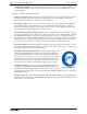
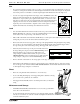
B a l l i s t i c P e n d u l u m / P r o je c t i l e L a u n c h e r General Operation of the Projectile Launcher General Operation of the Projectile Launcher Parts Trigger String Yellow Band in Window Indicates Range Label details Range setting slots (1 of 5) Trigger Thumbscrews Protractor Plumb Bob Muzzle Launcher Parts Ready • 4 Attach the included Trigger String to the hole in the Trigger. (For example, loop the string through the hole and tie the ends together.
Model No. ME-6830, ME-6831 General Operation of the Projectile Launcher Aim • If you have the Launcher mounted on the top position, you can adjust the angle of inclination above the horizontal by loosening the two thumbscrews and rotating the Launcher barrel to the desired angle. Use the plumb bob and the protractor on the label to select the angle. Tighten both thumbscrews when the angle is set. • You can ‘bore-sight’ through the barrel at a target, such as the ME-6853 Shoot-The Target.
B a l l i s t i c P e n d u l u m / P r o je c t i l e L a u n c h e r Ballistic Pendulum Theory Ballistic Pendulum Theory Overview The ballistic pendulum is a classic method of determining the velocity of a projectile. It is also a good demonstration of many of the basic principles of physics. The ball is fired into the ballistic pendulum, which then swings up a measured amount. From the height reached by the pendulum, you can calculate its gravitational potential energy.
Model No.
B a l l i s t i c P e n d u l u m / P r o je c t i l e L a u n c h e r The torque on the pendulum is thus: Ballistic Pendulum Theory I = – R cm Mg sin For small angles, , sin so if you make this substitution and solve for you get: MgR cm = – ------------------ I This angular equation is in the same form as the equation for linear simple harmonic motion: 2 k = – ---- x = – x m So if you compare the two equations, linear and angular, you can see that the pendulum exhibits simple harmon
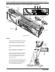
Model No. ME-6830, ME-6831 Ballistic Pendulum Theory Repairing the Plumb Bob Vertex If the string breaks that holds the plumb bob on the protractor of the Launcher, replace it with an equal length of nylon thread (such as the thread included in the ME-6802 Launcher Spares Kit). Make sure that the replacement string is long enough so that when the Launcher is inclined at an angle of 50°, the string extends well below the corner of the Launcher.
B a l l i s t i c P e n d u l u m / P r o je c t i l e L a u n c h e r 10 Ballistic Pendulum Theory • Overall error in measurement of ball velocity should not exceed 2.5% (exact method) or 10% (approximate method). • NOTE: Adjustable leveling feet are not necessary for good results. Small deviations from the horizontal will not cause significant error.
Model No. ME-6830 Exp. 1: Projectile Motion Exp. 1: Projectile Motion Equipment Needed Item Item Projectile Launcher and plastic ball Plumb bob and string Meter stick Carbon paper White paper Sticky tape Purpose The purpose of this experiment is to predict and verify the range of a ball launched at an angle. The initial speed of the ball is determined by shooting it horizontally and measuring the range of the ball and the height of the Launcher.
Projectile Launcher 2. Exp. 1: Projectile Motion Adjust the angle of the Projectile Launcher to zero degrees so the ball will by launched horizontally. Part A: Determining the Initial Horizontal Speed of the Ball 1. Put a plastic ball in the Projectile Launcher and use the ramrod to cock it at the long range position. Fire one shot to locate where the ball hits the floor. At that point, tape a piece of white paper to the floor.
Model No. ME-6830 Exp.
Projectile Launcher Exp.
Model No. ME-6830 Exp. 2: Projectile Motion Using Photogates Exp. 2: Projectile Motion Using Photogates Equipment Needed Item Item Projectile Launcher and plastic ball Plumb bob and string Photogate Head ME-9498A (2) Photogate Mounting Bracket ME-6821A PASCO Interface or Timer* PASCO Data acquisition software* Meter stick Carbon paper White paper Sticky tape *See the PASCO web site at www.pasco.com for information about PASCO interfaces, timers, and data acquisition software.
Projectile Launcher 4. E x p . 2 : P r o je c t i l e M o t i o n U s i n g P h o t o g a t e s Calculate the initial speed of the ball based on the 0.10 m distance between the photogates. Record the value. Data Table: Part A Table 2.1: Determine the Initial Speed Trial Time 1 2 3 Average Time Initial Speed Part B: Predicting the Range of a Ball Shot at an Angle 1. Keep the angle of the Projectile Launcher at the original angle above horizontal. 2.
Model No. ME-6830 Exp. 2: Projectile Motion Using Photogates Data Table: Part B Table 2.2: Confirm the Predicted Range Trial Distance 1 2 3 4 5 6 7 8 9 10 Average Total Distance Analysis 1. Calculate the percent difference between the predicted theoretical distance (“A”) and the actual average distance (“B”) when shot at an angle. A–B ------------- x100 A+B ------------2 1. Estimate the precision of the predicted range.
Projectile Launcher E x p .
Model No. ME-6830 E x p . 3 : P r o je c t i l e R a n g e v e r s u s A n g l e Exp. 3: Projectile Range versus Angle Equipment Needed Item Item Projectile Launcher and plastic ball Plumb bob and string Meter stick or measuring tape Box to make landing area same elevation as muzzle Graph paper Carbon paper White paper Sticky tape Purpose The purpose of this experiment is to determine how the range of the ball depends on the launch angle.
Projectile Launcher Exp. 3: Projectile Range versus Angle 2. Adjust the angle of the Projectile Launcher to 10 degrees. 3. Put a plastic ball into the Projectile Launcher and cock it to the medium or long range setting. Lau ow nch in Wind e. RT SHO GE RAN IUM MED GE RAN G LON GE RAN w Band Rang Yello ates Indic Use ! ! TION ION CAU ! UT LOKOK EL.
Model No. ME-6830 2. E x p . 3 : P r o je c t i l e R a n g e v e r s u s A n g l e Repeat the procedure and record the data in the Data Table. Table 3.2: Shooting off the Table Horizontal Distance Angle 10 20 30 40 50 60 70 80 1 2 3 4 5 Average Paper distance Total distance Analysis 1. Find the average of the five distances in each case and record the results in the Data Tables. 2.
Projectile Launcher 22 Exp.
Model No. ME-6830 E x p . 4 : P r o je ct i l e P a t h Exp. 4: Projectile Path Equipment Needed Item Item Projectile Launcher and plastic ball Movable vertical target board* Meter stick or measuring tape Sticky tape Graph paper Carbon paper White paper *The target board should be as tall as the distance from the muzzle to the floor.
Projectile Launcher 4. E x p . 4 : P r o je c t i l e P a t h Cover the target board with white paper. Tape carbon paper over the white paper. Procedure 1. Measure the vertical height from the floor to the muzzle and record the height in the Table 4.1. Mark this height on the target. 2. Measure the horizontal distance from the muzzle of the Launcher to the target board and record it in the Data Table. 3. Shoot the ball. 4. Move the target board about 10 to 20 cm closer to the Launcher. 5.
Model No. ME-6830 7. E x p . 4 : P r o je ct i l e P a t h Calculate the percent difference between the two initial speeds that were found using the different methods. Record the percent difference in Table 4.2. (To calculate the percent difference, let A be one of the initial speed values and let B be the other initial speed value.) A–B ------------------- x100 A + B ----------- 2 Data Table 4.2 Table 4.
Projectile Launcher E x p .
Model No. ME-6830 E x p . 5 : C o n se r v a t i o n o f E n e r g y Exp. 5: Conservation of Energy Equipment Needed Item Item Projectile Launcher and plastic ball Plumb bob and string Meter stick or measuring tape Sticky tape White paper Carbon paper Photogate Head ME-9498A (2) optional* Photogate Mounting Bracket ME-6821A optional* *Use the Photogates and Photogate Mounting Bracket with a PASCO Interface or Timer to measure the initial speed of the ball directly (see Experiment 2).
Projectile Launcher E x p . 5 : C o n se r v a t i o n o f E n e r g y Setup 1. Clamp the Projectile Launcher to a sturdy table or other horizontal surface. Mount the Launcher near one end of the table with the Launcher aimed away from the table. 2. Point the Launcher straight up and fire a test shot on medium range to make sure that the ball doesn’t hit the ceiling. (If it does, use the short range setting for this experiment or put the Launcher closer to the floor.) 3.
Model No. ME-6830 E x p . 5 : C o n se r v a t i o n o f E n e r g y Table 5.1 Trial Distance Trial 1 6 2 7 3 8 4 9 5 10 Distance Average Total distance Alternate Method for Determining the Initial Speed of the Ball (using photogates) 1. Attach the photogate mounting bracket to the Launcher and attach two photogates to the bracket. Check that the distance between the photogates is 0.10 m (10 cm). 2. Plug the photogates into an interface or a timer. 3.
Projectile Launcher E x p . 5 : C o n se r v a t i o n o f E n e r g y Part B: Measure the Height of the Ball 1. Adjust the angle of the Launcher to 90 degrees (straight up). 2. Shoot the ball on the medium range setting several times and then measure the maximum height attained by the ball. Record the maximum height in Table 5.3. 3. Determine the mass of the ball and record it in Table 5.3. Analysis 1. Calculate the initial kinetic energy and record it in Table 5.3. 2.
Model No. ME-6830 Exp. 6: Conservation of Momentum Exp. 6: Conservation of Momentum Equipment Needed Item Item Projectile Launcher and 2 plastic balls 2-D Collision Accessory Meter stick or measuring tape Sticky tape White paper, large sheet Carbon paper (2 or 3 sheets) Protractor Plumb bob and string Purpose The purpose of this experiment is to confirm that momentum is conserved for elastic and inelastic collisions in two dimensions.
Projectile Launcher Exp. 6: Conservation of Momentum Setup 1. Clamp the Projectile Launcher to a sturdy table. Mount the Launcher near one end of the table with the Launcher aimed inward toward the table. 2. Adjust the angle of the Projectile Launcher to zero degrees so the ball will be launched horizontally onto the table. 3. Cover the table with white paper (such as butcher paper). NOTE: The paper must reach the base of the Launcher. 4.
Model No. ME-6830 Exp. 6: Conservation of Momentum • Since the tape does not produce the same inelastic collision each time, it is only useful to record this collision once. 5. Use a plumb bob to locate on the paper the spot directly below the point of contact of the two balls. Mark this spot on the paper as the “point-of-contact” spot. Carefully remove the carbon paper from the white paper. Analysis The time of flight for each shot is the same because the vertical distance for each shot is the same.
Projectile Launcher Exp. 6: Conservation of Momentum C. Inelastic Collision 1. Draw straight lines from the “point-of-contact” spot to the dots made by the ‘inelastic collision’ shot. (There should be two lines.) 2. Measure from the “point-of-contact” to each of the dots made by the ‘inelastic collision’ shot. 3. Measure the angle from the centerline to the straight line for each dot of the ‘inelastic collision’ shot. 4.
Model No. ME-6830 E x p . 7 : V a r y t h e A n g le t o M a x i m iz e t h e H e i g h t Exp.
Projectile Launcher Exp. 7: Vary the Angle to Maximize the Height Setup 1. Clamp the Projectile Launcher to a sturdy table. Mount the Launcher near one end of the table with the Launcher aimed toward a wall about 2 meters from the table. 2. Use a vertical board to the protect the wall and cover the board with white paper. 3. Fire a test shot to see where the ball hits the board and tape a piece of carbon paper (carbon-side down) at that position. Procedure 1.
Model No. ME-6830 Exp. 8: Projectile Velocity—Approximate Method Exp. 8: Projectile Velocity—Approximate Method Equipment Needed Item Item Ballistic Pendulum/Projectile Launcher Steel ball C-clamp Mass balance String Purpose The muzzle velocity of the projectile launcher is determined by launching the ball into the ballistic pendulum and observing the angle to which the pendulum swings.
Projectile Launcher Exp. 8: Projectile Velocity—Approximate Method • NOTE: It may be easier to balance the pendulum on the edge of a ruler or similar object. 5. Reattach the pendulum to the upright, making sure that it is facing the right way. Be sure that the angle indicator is in front of the long pin of the pendulum. 6. Load the launcher, and then set the angle indicator to an angle one or two degrees less than the angle reached in step 2.
Model No. ME-6830 E x p . 9 : P r o je c t i l e V e l o c i t y — Ex a c t M e t h o d Exp. 9: Projectile Velocity—Exact Method Equipment Needed Item Item Ballistic Pendulum/Projectile Launcher and steel ball Ruler C-clamp Mass balance String Stopwatch Purpose The muzzle velocity of the projectile launcher is determined by launching the ball into the ballistic pendulum and observing the angle to which the pendulum swings.
Projectile Launcher 5. E x p . 9 : P r o je ct i l e V e l o c i t y — E x a c t M e t h o d Tie a loop in a piece of string, and hang the pendulum horizontally from the loop. (See Figure 9.1.) With the ball latched in position in the ball catcher, adjust the position of the pendulum in the loop until the pendulum balances. Measure the distance from the pivot point to this balance point, and record the distance as Rcm. String loop Rcm Figure 9.
Model No. ME-6830 E x p . 9 : P r o je c t i l e V e l o c i t y — Ex a c t M e t h o d Questions 1. Is there another way to measure the muzzle velocity that you could use to check your results? You may want to use that second method and compare the two answers. 2. What sources of error are there in this experiment? How much do these errors affect your result? 3.
Projectile Launcher 42 E x p .
Model No. ME-6830 E x p . 1 0 ( D e m o ) : D o 3 0 ° a n d 6 0 ° G iv e t h e S a m e R a n g e ? Exp. 10 (Demo): Do 30° and 60° Give the Same Range? Equipment Needed Item Item Projectile Launcher and steel ball Box to make landing area same height as muzzle Purpose The purpose of this demonstration is to confirm that the range of a ball launched at 30° is the same as one launched at 60° if the ball lands at the same height from which it was launched.
Projectile Launcher 44 Exp. 10 (Demo): Do 30° and 60° Give the Same Range? 2. Change the angle of the Launcher to 60° and shoot the ball again. Call attention to the fact that the ball again lands on the box (confirming that the ranges are the same). 3. Change the angle to 45° and shoot the ball again to show that the ball now lands further away, missing the box. 4.
Model No. ME-6830 Exp. 11 (Demo): Simultaneous Shots at Different Speeds Exp. 11 (Demo): Simultaneous Shots at Different Speeds Equipment Needed Item Projectile Launcher (2) and plastic ball (2) Purpose The purpose of this demonstration is to confirm that regardless of the initial speed of projectiles fired horizontally, the projectiles will hit the floor at the same time. Theory Two projectiles are shot horizontally from the same height, y. The muzzle speeds of the two projectiles are different.
Projectile Launcher 46 Exp.
Model No. ME-6830 Exp. 12 (Demo): Shooting Through Hoops Exp. 12 (Demo): Shooting Through Hoops Equipment Needed Item Item Projectile Launcher and plastic ball Ring clamp on stand (5) Photogate Head ME-9498A (2) optional Photogate Mounting Bracket ME-6821A optional Meter stick Two-meter stick Purpose The purpose of this demonstration is to confirm that the part of a projectile is parabolic.
Projectile Launcher 2. Exp. 12 (Demo): Shooting Through Hoops Calculate and record the horizontal and vertical positions of the ball each 1/10 second until the vertical position is zero. Table 10.1: X- and y-positions x = v0t (cm) t (sec) y = y0 - (1/2)gt2 (cm) 0.1 0.2 0.3 0.4 0.5 Lay the two-meter stick on the floor in a straight line away from the Launcher. Remove the back mounting screw from the Launcher base so that the back of the Launcher can rotate upward.
Model No. ME-6830 E x p . 1 3 ( D e m o ) : E l a s t i c a n d I n e la s t i c C o l l i s i o n s Exp. 13 (Demo): Elastic and Inelastic Collisions Equipment Needed Item Projectile Launcher and plastic or steel ball Purpose The purpose of this demonstration is to show the difference in kinetic energy transfer between an elastic collision and an inelastic collisions. Theory The amount of kinetic energy transferred between colliding objects depends on the elasticity of the collision.
Projectile Launcher 50 Exp.
Model No. ME-6830 Teacher’s Guide Teacher’s Guide Exp. 1: Projectile Motion NOTE: For best results, make sure that the Launcher is securely clamped to a sturdy table. Any movement of the Launcher will result in inconsistent data. The muzzle speed of the Launcher tested was 6.5 m/s (on the long range setting). To find the range at the chosen angle, it is necessary to solve the quadratic equation given in the Theory section.
Ballistic Pendulum/Projectile Launcher Teacher’s Guide Exp. 3: Projectile Range Versus Angle Procedure • Shooting off a level surface: 4.5 4 3 Range (m) 3.5 2.5 2 1.5 1 0.5 0 0 • 10 20 30 40 50 Angle (degrees) 60 70 80 90 Shooting off a table: 6 5 4 Range (m) 3 2 1 0 0 • 10 20 30 40 50 Angle (degrees) 60 70 80 90 NOTE: The curves show the calculated ranges in each case. The data points are the actual measured ranges.
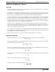
Model No. ME-6830 2. Teacher’s Guide Vertical distances were measured from the ground up for this graph. The intercept is the height of the launcher above the ground when done this way. Vertical Distance (m) 0.25 0.2 0.15 0.1 f(x) = -1.181345E-1*x + 2.609457E-1 R^2 = 9.997926E-1 0.05 0 0 0.2 0.4 0.6 0.8 1 1.2 1.4 1.6 Horizontal Distance Squared (m^2) 1.8 2 3. The slope (measuring from the ground) is -0.118 for this example.
Ballistic Pendulum/Projectile Launcher Teacher’s Guide Exp. 6: Conservation of Momentum in Two Dimensions Setup • If possible, use medium range setting instead of the short range setting. The medium range setting gives more predictable results than the short-range setting. Analysis • Results for the x component of momentum should be within 5% of initial values. The total y component should be very small compared to the x component. Questions 1. Momentum is conserved on both axes. 2.
Model No.
Ballistic Pendulum/Projectile Launcher Teacher’s Guide Calculations • Use the equations given in the theory section for the approximate method. Questions 1. The best other method of measuring velocity is described in the first part of experiment 1. 2. The greatest source of error is the equation used. This is an approximate equation, based on the assumption that the masses involved are point masses.
Model No. ME-6830 Technical Support Technical Support For assistance with any PASCO product, contact PASCO at: Address: PASCO scientific 10101 Foothills Blvd. Roseville, CA 95747-7100 Phone: 916-786-3800 (worldwide) 800-772-8700 (U.S.) Fax: (916) 786-7565 Web: www.pasco.com Email: support@pasco.com For more information about the Ballistic Pendulum/Projectile Launcher and the latest revision of this Instruction Manual, visit the PASCO web site and enter ME-6830 or ME-6831 into the Search window.
Ballistic Pendulum/Projectile Launcher 58 012-05375C Technical Support ®