
User's Manual


89
012-05892A AC/DC Electronics Laboratory
®
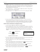
➈ Connect a black banana plug patch cord from the negative (-) terminal of the Power Amplifier to
the negative terminal of the DC power supply.
➉ Put alligator clips on the banana plugs of the Voltage Sensor. Connect the red lead of the sensor
to the component spring at the right end of the 330 Ω resistor and the black lead to the left end of
the resistor.
11
Connect the red lead (+) from the Power Amplifier with an alligator clip to the bottom of the
22 kΩ resistor.
PART III: Data Recording
➀ Turn on the DC power supply and adjust its voltage output to exactly +5 Volts.
➁ Turn on the power switch on the back of the power amplifier.
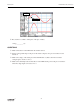
➂ Click the “ON” button ( ) in the Signal Generator window.
• Observe the behavior of the LED. Write a description of what you observe.
➃ Click the “REC” button ( ) to begin recording data. Recording will stop automatically after
200 samples are measured.
• Run #1 will appear in the Data list in the Experiment Setup window.
3 VOLTS MAX
C
W
EM-8656
AC/DC ELECTRONICS LABORATORY
C
B
E
–
–
+
to
Ground
to
Power Amp
to
Power Supply
+5V
330 Ω
Res
22 kΩ Res
Cathode
LED
to Channel A
Transistor 2N3904