
User's Manual


80
AC/DC Electronics Laboratory 012-05892A
®
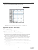
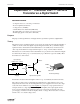
• The top trace is the voltage across the “load” resistor. (The other trace is the Output Voltage.)
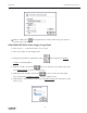
➃ Click the “STOP” button.
➄ Click the “Data Snapshot” button ( ) for the “B” channel. Enter Data Cache Information for
“Long Name”, “Short Name”, and Units as needed to save the data for analysis.
➅ Click the “OFF” button ( ) in the Signal Generator window.
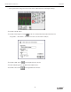
➆ Put the 470 µF capacitor in parallel with the 100 Ω resistor.
➇ Click the “ON” button ( ) in the Signal Generator window.