
User's Manual


79
012-05892A AC/DC Electronics Laboratory
®
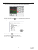
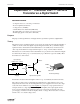
➅ Put the 100 Ω resistor
diagonally between the upper
left corner and the lower right
corner of the square of
diodes.
➆ Use a five inch wire lead to
connect a component spring
next to the top banana jack
and the component spring at
the RIGHT end of the first
diode.
➇ Use a ten inch wire lead to
connect a component spring next to the bottom banana jack and the component spring at the
LEFT end of the second (bottom) diode.
channel A
black
red
red
black
100 Ω
R
L
Power Amplifier
➄ Connect the alligator clip of the red voltage sensor lead to the component spring at the upper left
corner of the diode square (called a “bridge”). Connect the alligator clip of the black voltage
sensor lead to the component spring at the lower right corner of the diode bridge.
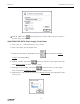
PART III: Data Recording - Four Diode Bridge Rectifier
➀ Turn on the power switch on the back of the power amplifier.
➁ Click the “ON” button ( ) in the Signal Generator window.
➂ Click the “MON” button ( ) to begin data monitoring.
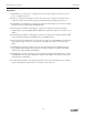
EM-8656
AC/DC ELECTRONICS LABORATORY
to Power Amp
(4) Diode
Res
to Channel B