
User's Manual


75
012-05892A AC/DC Electronics Laboratory
®
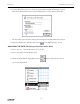
➃ Click the “STOP” button.
➄ Click the “Data Snapshot” button ( ) for the “B” channel. Enter Data Cache Information for
“Long Name”, “Short Name”, and Units as needed to save the data for analysis.
➅ Click the “OFF” button ( ) in the Signal Generator window.
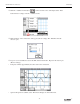
PART IIIB: Data Recording – Diode and Capacitor
➀ Add the 470 µF capacitor in parallel to the 100 Ω resistor. Carefully bend the leads of the
capacitor so they can fit in the same component springs as the resistor. Put the shorter wire lead
of the capacitor into the right hand component spring. The capacitor acts as a “filter”.
100 Ω
black
red
Power Amplifier
channel A
red
black
Diode
•
•
RL
•
••
•
470 µF
C
10 Ω
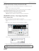
➁ Click the “ON” button ( ) in the Signal Generator window.
➂ Click the “MON” button ( ) to begin data monitoring.
• The top trace is the voltage across the “load” resistor.