
User's Manual


74
AC/DC Electronics Laboratory 012-05892A
®
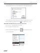
➄ Click on the Signal Generator window, or select it from the Experiment menu. Click on the
frequency to highlight it. Type in “60” as the new frequency, and press “enter” on the keyboard.
PART II: Sensor Calibration and Equipment Setup
• You do not need to calibrate the sensors.
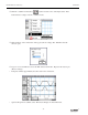
➀ Replace the 1 kΩ resistor with a 100 Ω resistor in the component springs near the bottom banana
jack. The 100 Ω resistor will be the “load” resistor.
100 Ω
black
red
Power Amplifier
channel A
red
black
Diode
•
•
R
L
➁ Get the following items for use later in this experiment: 470 microfarad (µF) capacitor, 10 ohm
resistor, three 1N-4007 diodes.
PART IIIA: Data Recording – Single Diode Rectifier
➀ Turn on the power switch on the back of the power amplifier.
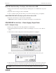
➁ Click the “ON” button ( ) in the Signal Generator window.
➂ Click the “MON” button ( ) to begin data monitoring.
• The “OUT” channel trace on the Scope display is the Output Voltage from the Power Amplifier.
The “B” channel trace is the voltage across the resistor.
➤ NOTE: The trace of the Output Voltage has been offset downward so both traces can be seen.