
User's Manual


73
012-05892A AC/DC Electronics Laboratory
®
PART IIIB: Data Recording - Rectifying a Sine Wave with a LED
➀ Remove the diode from the component springs. Carefully place a colored LED in the component
springs.
➁ Repeat the data recording procedure as in Part IIIA.
➂ After you finish recording data, turn off the power switch on the back of the power amplifier.
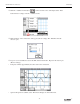
ANALYZING THE DATA: Rectifying a Sine Wave with a LED
➀ Repeat the data analysis procedure that followed Part IIIA.
• Optional: If a printer is available, select “Print Active Display” from the File menu.
PROCEDURE A: Unit Four – Power Supply, Single Diode
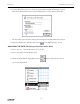
PART I: Computer Setup
➀ Remove the voltage sensor from Analog Channel A of the interface.
➁ Expand the Experiment Setup window to full size by clicking the “Zoom” box or the “Restore”
button.
➂ Click on the icon of the Voltage Sensor under Analog Channel A to highlight it.
Press the “delete” key on the keyboard. Click “OK” in the alert dialog window that opens.
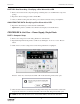
➃ Delete the data caches from the Data list in the Experiment Setup window. Click on a data cache
and press the “delete” key on the keyboard. Click “OK” in the alert dialog window that opens.
➤ NOTE: To delete both data caches at once, hold down the Shift key and select both data caches.