
User's Manual


60
AC/DC Electronics Laboratory 012-05892A
®
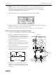
➄ Connect the alligator clips of the Channel B voltage sensor to the wires at both ends of the 1 k
resistor.
➅ Connect banana plug patch cords from the output of the Power Amplifier to the banana jacks on
the AC/DC Electronics Lab Board.
Part III: Data Recording - Diode and 1 k Resistor
➀ Turn on the power switch on the back of the power amplifier.
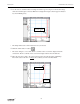
➁ Click the “ON” button ( ) in the Signal Generator window.
➂ Click the “REC” button ( ) to begin data recording.
• Data recording will end automatically after 250 samples are measured. Run #1 will appear in the
Data list in the Experiment Setup window.
➃ Click the “OFF” button ( ) in the Signal Generator window. Turn off the switch on the back
of the power amplifier.
ANALYZING THE DATA: Diode and 1 kΩ Resistor
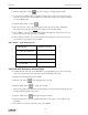
➀ Click the “Autoscale” button ( ) to resize the Graph to fit the data.
• The vertical axis shows Current in milliamps based on a calculation using the voltage drop across
the 1 kΩ resistor. The horizontal axis shows Voltage across the diode.
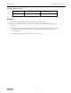
➁ Select “Save As…” from the File menu to save your data. Select “Print Active Display” from the
File menu to print the Graph.
➂ Click the “Magnifier” button ( ). The cursor changes to a magnifying glass shape.