
User's Manual


27
012-05892A AC/DC Electronics Laboratory
®
EQUIPMENT NEEDED:
– AC/DC Electronics Lab Board: 1 kW Resistor, 100 Ω Resistor,
2N3904 Transistor (NPN), Wire Leads
– (2) D-cell Batteries
– Digital Multimeter (DMM)
– Optional: additional Digital Multimeter
Purpose
The purpose of this lab will be to experimentally determine some of the operating characteristics
of a transistor.
Procedure
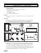
➀ Connect the circuit shown in Figure 10.1a using the 2N3904 Transistor you’ve been supplied. Resistor
R
1
= 1 K Ω and resistor R
2
= 100 Ω. Use Figure 10.1b as a reference along with Figure 10.1a as you
record your data. Note the leads on the transistor as marked next to the socket in the drawing.
➁ Adjust the potentiometer carefully until the reading between points A and B is approximately
0.002 volt (2.0 mv). Now read the voltage between points C and D. Record these readings in
your data table. Note that V
AB
divided by R
1
gives the current flowing to the base of the transis-
tor, while V
CD
divided by R
2
gives the current flowing in the collector part of the circuit.
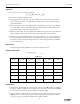
➂ Adjust the potentiometer to give V
AB
the following readings, each time reading and recording the
corresponding V
CD
: 0.006, 0.010, 0.015, 0.020, 0.025, 0.030, 0.035, 0.040, 0.045, 0.050, 0.055,
0.060, 0.080, 0.100, 0.150, 0.200, 0.250 volts. Also set V
AB
to 0.000 volts.
Experiment 10: Transistors
Figure 10.1a
Figure 10.1b
R
1
C
W
C
B
E
–
+
–
+
Battery
Battery
AB
CD
b
c
e
R
2
R
2
R
1
A
B
C
D
2N3904
b
e
c
Transistor, top view
Socket
2N3904
➤ CAUTION: Connecting the
transistor incorrectly can destroy
the transistor.