
User's Manual


25
012-05892A AC/DC Electronics Laboratory
®
Experiment 9: Diodes
EQUIPMENT NEEDED:
– AC/DC Electronics Lab Board: 1 KΩ Resistor, 330 Ω Resistor, 1N4007 Diode, Wire Leads
– Digital Multimeter (DMM)
– (2) D-cell Batteries
Purpose
The purpose of this lab will be to experimentally determine some of the operating characteristics
of semiconductor diodes.
Procedure
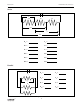
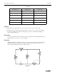
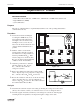
À
Connect the circuit shown in Figure
9.1a using the 1N4007 diode you’ve
been supplied and the 1 KΩ resistor.
Use Figure 9.1b as a reference along
with Figure 9.1a as you record your
data. Note the direction that the diode is
oriented, with the dark band closer to
point B.
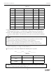
Á With the “switch” closed and the
current flowing, adjust the potentiom-
eter until there is a voltage of 0.05 volt
between points B and C (V
BC
). Mea-
sure the voltage across the diode (V
AB
).
Record your values in the left-hand side
of Table 9.1 under “Forward Bias”.
 Adjust the potentiometer to attain the
following values for V
BC
: 0.1, 0.2,
0.3,.....2.0 volts. Record the two
voltages for each case.
à Remove the 1 KΩ resistor and replace it with a 330-Ω
resistor. Repeat steps 3 & 4, going from a voltage of 0.3,
0.4,.....2.0 volts. Record V
BC
and V
AB
in each case.
Ä Reverse the orientation of the diode. Set the diode voltage
(V
AB
) to the values 0.5, 1.0,....3.0 volts. Measure the
resistor voltage (V
BC
) in each case. Record these values in
the columns labeled “Reverse Bias”.
Analysis
À Determine the current flow (I) in each setting by dividing the voltage across the resistor
(V
BC
) by the resistance. Where you switched resistors, be sure to change the divisor.
Á Construct a graph of Current (vertical axis) vs the Voltage across the diode, with the graph
extending into the 2nd quadrant to encompass the negative voltages on the diode.
C
W
–
+
–
+
Battery
Battery
Figure 9.1a
Figure 9.1b
AB
C
1N4007
R
Res
Diode
A
BC
Switch