
User's Manual


24
AC/DC Electronics Laboratory 012-05892A
®
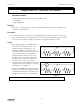
Table 8.1
Trial Resistance Capacitance
1
2
3
4
5
6
7
8
t
C
t
D
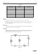
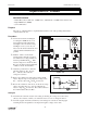
⑧ Replace the 100 µF capacitor with a 330 µF capacitor. Repeat step 7, recording the charging
and discharging times in Table 8.1. If a third value is available, include it in the data table, too.
⑨ Return to the original 100 µF capacitor, but put a 220 kΩ resistor in the circuit. Repeat step 7,
recording your data in Table 8.1. If a third resistor is provided, use it in the circuit, recording the
data.
➤ NOTE:
➀ What is the effect on charging and discharging times if the capacitance is increased? What
mathematical relationship exists between your times and the capacitance?
➁ What is the effect on charging and discharging times if the resistance of the circuit is
increased? What mathematical relationship exists between your times and the resistance?
➉ Return to the original 100 kΩ resistor, but use the 100 µF capacitor in series with the 330 µF
capacitor. Repeat step 7, recording your results in Table 8.2.
11
Now repeat step 7, but with the 100 µF and the 330 µF capacitors in parallel.
R = __________ C
1
= __________C
2
= __________
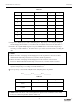
➤ NOTE: What is the effect on the total capacitance if capacitors are combined in series? What
if they are combined in parallel? (Refer to Table 8.2).
Type of Circuit
Series
Parallel
t
C
t
D
Table 8.2