
User's Manual


16
AC/DC Electronics Laboratory 012-05892A
®
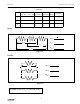
➂ Now connect the parallel circuit below, using all three resistors. Measure the voltage across
each of the resistors and the combination, taking care with the polarity as before.
➤ NOTE: Keep all three resistors connected throughout the time you are making your
measurements. Write down your values as indicated below.
Parallel
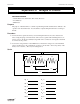
➃ Now connect the circuit below and measure the voltages. You can use the resistance read-
ings you took in Experiment 4 for this step.
Combination
➄ Use the three unequal resistors that you used in Experiment 4 to construct the circuits shown
below. Make the same voltage measurements that you were asked to make before in steps 1
to 4. Use the same resistors for A, B and C that you used in Experiment 4.
➤
➤
V
1
R
1
R
2
R
3
-
+
R
123
=
R
1
=
R
2
=
R
3
=
V
1
=
V
2
=
V
123
=
V
3
=
Figure 5.2
Figure 5.3
➤
➤
➤
➤
➤
➤
-
+
R
2
R
1
R
3
V
1
V
23
V
123
R
123
=
R
1
=
V
1
=
V
23
=
V
123
=
R
23
=