
User's Manual


117
012-05892A AC/DC Electronics Laboratory
®
Procedure
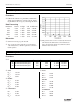
Equal Resistors:
Series
measurement Resistance Voltage
1 100 0.523
2 100 0.528
3 100 0.527
12 200 1.051
23 200 1.055
123 300 1.578
Parallel
measurement Resistance Voltage
1 33.33 1.565
2 33.33 1.565
3 33.33 1.565
123 33.33 1.565
Combination
measurement Resistance Voltage
1 100 1.049
23 50 0.529
123 150 1.578
Different Resistors:
Series
measurement Resistance Voltage
A 100 0.157
B 330 0.526
C 560 0.897
AB 430 0.685
BC 890 1.423
ABC 990 1.581
Parallel
measurement Resistance Voltage
A 67.49 1.574
B 67.49 1.574
C 67.49 1.574
ABC 67.49 1.574
Combination
measurement Resistance Voltage
A 100.00 0.509
BC 207.64 1.07
ABC 307.64 1.579
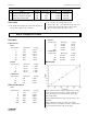
Discussion
In any series circuit, the voltage is distributed according
to the size of the resistors. (Notice that the graph above,
of the data from the second series circuit, shows this
direct relationship.)
In any parallel circuit, the voltage is the same across all
elements.
In the combination circuit, the voltage acts as if the
parallel resistors were actually one resistor, which is then
in series with the first. The rules are the same.
Discussion
➀ The actual value matches the coded value much more
closely than required by the tolerances.
Colors coded measured % error tolerance
A brown-black-brown-gold 100 98.9 -1.10% ±0.05%
B orange-orange-brown-gold 330 330 0.00% ±0.05%
C green-blue-brown-gold 560 561 0.18% ±0.05%
➁-➃ In series, the resistances are added.
R = R
1
+ R
2
+ R
3
+ ...In parallel, the reciprocals of the
resistances are added. 1/R = 1/R
1
+ 1/R
2
+ 1/R
3
+...
This is evidenced in all the data sets above.
Exp 5- Voltages in Circuits