
Datasheet


PowertothePhotonissuppliedviatheon-boardUSBMicroBconnectorordirectlyviatheVINpin.
IfpowerissupplieddirectlytotheVINpin,thevoltageshouldberegulatedbetween3.6VDCand
5.5VDC.WhenthePhotonispoweredviatheUSBport,VINwilloutputavoltageofapproximately
4.8VDCduetoareversepolarityprotectionseriesschottkydiodebetweenV+ofUSBandVIN.
Whenusedasanoutput,themaxloadonVINis1A.3V3canalsobeusedasanoutput,buthasa
limitedoverheadofonly100mAavailable.(PleaserefertoAbsoluteMaximumRatingsformore
info).
Typicalaveragecurrentconsumptionis80mAwith5V@VINwithWi-Fion.Deepsleepquiescent
currentistypically80uA(PleaserefertoRecommendedOperatingConditionsformoreinfo).
WhenpoweringthePhotonfromtheUSBconnector,makesuretouseaqualitycabletominimize
IRdrops(currentxresistance=voltage)inthewiring.Ifahighresistancecable(i.e.,lowcurrent)is
used,peakcurrentsdrawnfromthePhotonwhentransmittingandreceivingwillresultinvoltage
sagattheinputwhichmaycauseasystembrownoutorintermittentoperation.Likewise,the
powersourceshouldbesufficientenoughtosource1Aofcurrenttoprovideanadequateamount
ofcurrentoverhead(especiallyifpoweringadditionalcircuitryoffofVIN).
Warning:WhenpoweringthePhotonfromlongwiresonUSBandVIN,careshouldbetakento
protectagainstdamagingvoltagetransients.FromtheRichtekdatasheet:
Whenaceramiccapacitorisusedattheinputandthepowerissuppliedbyawalladapterthroughlong
wires,aloadstepattheoutputcaninduceringingattheinput,VIN.Atbest,thisringingcancoupletothe
outputandbemistakenasloopinstability.Atworst,asuddeninrushofcurrentthroughthelongwirescan
potentiallycauseavoltagespikeatVINlargeenoughtodamagethepart.
Toavoidthesevoltagespikes,keepinputwiringasshortaspossible.Iflongwiresareunavoidable,
itisadvisabletoadda5.1VzenerdiodeorsimilartransientsuppressiondevicefromVINtoGND.
Anothertechniqueisaddingmorecapacitancetotheinputusinganelectrolyticcapacitor.Please
refertoAN-88byLinearforagooddiscussiononthistopic.
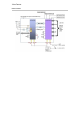
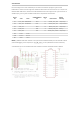
TheRFsectionofthePhotonisafinelytunedimpedancecontrollednetworkofcomponentsthat
optimizetheefficiencyandsensitivityoftheWi-Ficommunications.
AnRFfeedlinerunsfromthePØmoduleintoaSPDTRF-switch.LogiclevelcontrollinesonthePØ
moduleselectwhichofthetwoportsoftheRF-switchisconnectedtotheRFfeedline.A100pF
decouplingcapacitorislocatedoneachcontrolline.OneportisconnectedtoaPCBceramicchip
antenna,andtheotherisconnectedtoaU.FLconnectorforexternalantennaadaptation.The
defaultportwillbesettothechipantenna.
Additionally,auserAPIisavailabletoswitchbetweeninternal,externalandevenanautomatic
modewhichcontinuouslyswitchesbetweeneachantennaandselectsthebestsignal.AllthreeRF
portsontheRF-switchhavea10pFRFqualityDC-blockingcapacitorinserieswiththem.These
effectivelypass2.4GHzfrequenciesfreelywhileblockingunwantedDCvoltagesfromdamaging
theRF-switch.AllRFtracesareconsideredastinytransmissionlinesthathaveacontrolled50ohm
impedance.
Thechipantennaisimpedancematchedtothe50ohmRFfeedlineviaaPinetworkcomprisedof
threeRFinductors(1series,2shunt).ThesevaluesarequitespecifictothePhotonduetothePCB
constructionandlayoutoftheRFsection.EvenifthePhoton'slayoutdesigniscopiedexactly,to
achievethebestperformanceitwouldbeworthre-examiningthePinetworkvaluesonactual
samplesofthePCBinquestion.
POWER
RF