598M 4877 Valve Controller Operating Instruction Manual
Valve Controllers Preface Related Instructions — 2 Scope — 2 Applications — 2 Explanation of Symbols — 3 Safety Information — 3 Intended Usage — 3 Unpack Carefully — 3 Cleaning & Maintenance — 4 Provisions for Lifting and Carrying — 4 General Specifications — 4 Electrical Ratings— 4 Environmental Conditions— 4 Installation General Instructions — 5 Main power switch — 5 Air Supply — 6 Reactor Outlet — 6 Protective Fuses — 6 Fuses— 6 Parts List Fuses — 7 Control Cables — 7 Mains Supply Cords — 7 Valve Control
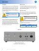
Valve Controllers Explanation of Symbols I On position O Off Position ~ Alternating Current (AC) This CAUTION symbol may be present on the Product Instrumentation and literature. If present on the product, the user must consult the appropriate part of the accompanying product literature for more information. Protective Earth (PE) terminal. Provided for connection of the protective earth (green or green/yellow) supply system conductor.
Valve Controllers Cleaning & Maintenance Periodic cleaning may be performed on the exterior surfaces of the controller with a lightly dampened cloth containing mild soap solution. All power should be disconnected and the power cord should be unplugged when cleaning the 4877 Valve Controller. There are no user serviceable parts inside the product other than what is specifically called out and discussed in this manual.
Valve Controllers Installation General Instructions Set the controller near the reactor on a sturdy bench or table where there is convenient access to an electrical outlet capable of carrying the appropriate current. Leave a space of at least twelve inches between the controller and the reactor so that the controller will not be affected by radiant heat. Plug the power cord into a properly grounded electrical supply outlet.
Valve Controllers Air Supply Valve Control Connect a dry air supply to the 1/4” Male Tube connector provided on the rear panel of the 4877 Valve Controller. The operating pressure of the air supply is determined by the air actuated valves supplied with your reactor system. The controller and the supplied tubing are limited to a maximum working pressure of 105psig.
Valve Controllers Parts List Fuses Fuse Rating Part Number Main Fuse(s) Fast acting, 3 Amp, 250VAC 139E24 Warning: For continued protection against possible hazard, replace fuses with same type and rating of fuse. Control Cables Part number Description A1120E Control Cable 16ft.
Revision 04/04/12