
User Manual
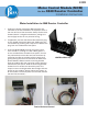

MCM Installation
Parr Instrument Company
6
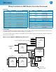
Motor Control Module (MCM) Wiring Schematic
P3
1 - WHITE
2
2 - BLACK
3 - WHITE
4 - BLACK
1
4 +
6 -
11 +
REMOTE
B
M
10
RPM DPM
1
2
3
4
- 5
+ 6
RS485
P2
10
LOCAL
1588E
ISOLATER
9
10
7
8
7
F -
P1
12 -
5 OUT
6
TO TERMINAL
CONTROL BOARD
BLOCK
REF
A1250EEE OR
6
5
DC SPEED
9
9 -
10 +
2084E
T
A1220EEE
REF
8
9
REF
FROM A2106E RPM INPUT HARNESS
12
11
2065E
N
L
IN
OUT
N
L
IN
SIGNAL
ADJUSTABLE
POTENTIOMETER
REF
1
2
3
4
- 5
+ 6
1588E
ISOLATER
9
10
N
L
IN
OUT
SIGNAL
1
2
3
4
- 5
+ 6
1588E
ISOLATER
9
10
N
L
IN
OUT
SIGNAL
115V
JUMPER SETTING
230V
JUMPER SETTING
BLACK
RED
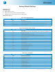
Pin Outs:
2084E Color: Attaches to:
Pin 1 Black Terminal Block 5
Pin 2 White Terminal Block 2
Pin 3
Pin 4 White A1695E Excit Board
Pin 5
Pin 6 Black A1695E Excit Board
Pin 7
Pin 8
Pin 9 Black 1588E Terminal 5
Pin 10 Red 1558E Terminal 6
Pin 11 White Terminal Block 4
Pin 12 Black Terminal Block 3
1588E Color: Attaches to:
Pin 1 White Terminal Block 2
Pin 2 Jumper
Pin 1 on 115V
Pin 3 on 230V
Pin 3 Jumper
Pin 4 on 115V
Pin 2 on 230V
Pin 4 Black Terminal Block 2
Pin 5 Black 2084E Terminal 9
Pin 6 Red 2084E Terminal 10
Pin 7
Pin 8
Pin 9 Black Speed Control F-
Pin 10 Orange
Local/Remote Switch
Top Position
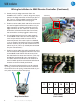
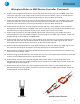
Final Steps:
Close the controller and replace the two screws on the top plate. Plug the 4848 controller back in, and turn it on.
The RPM display should read zero when the motor is not turning.
It is useful to check that the settings on the display are set correctly. Check these against the defaults listed in the
back of these instructions.
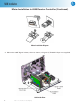
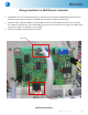
Wiring Installation in 4848 Reactor Controller (Continued)