594M A2200E Flow Controller Operating Instruction Manual
Flow Controller Preface Related Instructions — 3 Scope — 3 Applications — 3 Customer Service — 3 Explanation of Symbols — 4 Safety Information — 4 Intended Usage — 4 Unpack Carefully — 4 Cleaning & Maintenance — 5 Provisions for Lifting and Carrying — 5 General Specifications — 5 Electrical Ratings— 5 Environmental Conditions— 5 Installation General Instructions — 6 Inputs/Outputs — 6 Main power switch — 7 Protective Fuses — 7 Fuses— 7 Instructions for the A2200E Flow Controller Navigating the Menus — 9 Con
Flow Controller Preface Scope Related Instructions These instructions cover the installation and operation of Parr Model A2200E Flow Controller as used with Parr Laboratory Reactors and Pressure Vessels. The users should study the instructions carefully before using any of these controllers so that they will fully understand the capabilities of this equipment and the safety precautions to be observed in its operation.
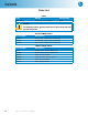
Flow Controller Explanation of Symbols I On position O Off Position ~ Alternating Current (AC) This CAUTION symbol may be present on the Product Instrumentation and literature. If present on the product, the user must consult the appropriate part of the accompanying product literature for more information. Protective Earth (PE) terminal. Provided for connection of the protective earth (green or green/yellow) supply system conductor.
Flow Controller Cleaning & Maintenance Environmental Conditions Periodic cleaning may be performed on the exterior surfaces of the controller with a lightly dampened cloth containing mild soap solution. All power should be disconnected and the power cord should be unplugged when cleaning the A2200E Controller. This instrument is intended to be used indoors. There are no user serviceable parts inside the product other than what is specifically called out and discussed in this manual.
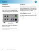
Flow Controller Installation Inputs/Outputs General Instructions Up to 4 MFC I/O connectors and corresponding meters can be supplied with each A2200E. The A2200E I/O’s are to only be used with Parr approved controllers. The interface is designed for mass flow controllers which are specified during the ordering process. An interface cable is supplied for each I/O.
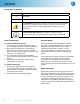
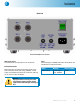
Flow Controller Back side Back View A2200E Flow Controller Main power switch This switch will cut off power to the controller. Protective Fuses Main fuses are mounted on the back panel of the flow controller. These fast acting, 250VAC, 4 amp fuses are intended to protect the controller and supply in case of a fault condition. Fuses The following are A2200E Controller fuses which are intended to be field serviceable.
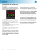
Flow Controller Instructions for the A2200E Flow Controller Each A2200E can be supplied with up to four I/O’s. These I/O’s are used to interface the Mass Flow Controllers on the corresponding reactor system. The SP indication displays the current set point value which relates to a scaled linear output voltage or current transmitted to the corresponding mass flow controller. The set point can be changed by pressing the Return key (Circular Arrow) once while in the operation mode.
Flow Controller Navigating the Menus Setup Mode - SEtP To enter setup mode, uLoc = 20 To navigate to the menu select mode, hold down the Return key and press the Up Arrow key. To navigate in the select mode press the Up Arrow or Down Arrow key and then the Return key to enter the chosen mode. Once in the desired mode press the Return key to navigate to each parameter, use the Up Arrow or Down Arrow to change the respective parameter value.
Flow Controller Parts List Fuses Fuse Rating Part Number Main Fuse(s) Fast acting, 4 Amp, 250VAC 1434E Warning: For continued protection against possible hazard, replace fuses with same type and rating of fuse.
Revision 08/08/11