
T-28 Trojan 1.1m Manual

6
EN
Model Assembly Continued
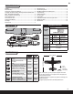
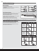
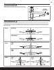
Control Horn and Servo Arm Settings
The table to the right shows the factory settings for the control horns and servo
arms. Fly the aircraft at factory settings before making changes.
After fl ying, you may choose to adjust the linkage positions for the desired
control response. See the table to the right.
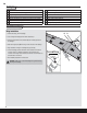
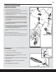
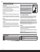
Clevis Installation
• Pull the tube from the clevis to the linkage.
• Carefully spread the clevis, then insert the clevis pin into the desired hole in
the control horn.
• Move the tube to hold the clevis on the control horn.
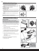
Control Surface Centering
After assembly and transmitter setup, confi rm that the control surfaces are
centered. If the control surfaces are not centered, mechanically center the
control surfaces by adjusting the linkages.
If adjustment is required, turn the clevis on the linkage to change the length of
the linkage between the servo arm and the control horn.
After binding a transmitter to the aircraft receiver, set the trims and
sub-trims to 0, then adjust the clevises to center the control surfaces.
1.
2.
3.
4.
5.
6.
Horns Arms
Elevator
Ailerons
Rudder
More control throw Less control throw
Nose
gear