Sukhoi SU-29MM Instruction Manual / Bedienungsanleitung Manuel d’utilisation / Manuale di Istruzioni
EN NOTICE All instructions, warranties and other collateral documents are subject to change at the sole discretion of Horizon Hobby, LLC. For up-to-date product literature, visit www.horizonhobby.com and click on the support tab for this product.
EN Table of Contents Control Direction Test ...................................................................................... 9 AS3X Control Direction Test........................................................................... 10 Flying Tips .................................................................................................... 11 Guidlines for Flying 3D .................................................................................. 12 Motor Service ................................
EN Transmitter and Receiver Binding 9 Binding Procedure Reference Table IMPORTANT: The included AR636 receiver has been programmed for operation in only this aircraft. 1. Refer to your transmitter instructions for binding to a receiver. For a list of compatible DSM2/DSMX transmitters, please visit www.bindnfly.com. 3. Make sure the transmitter controls are at neutral, the throttle is in the low position and the aircraft is immobile. * 2. Ensure the transmitter is powered off. 4.
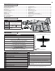
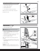
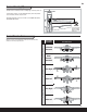
EN Landing Gear Installation B 1. Install the landing gear strut (A) as shown. A 2. Install the U-cover (B) on the fuselage. 3. Install the fairings (C) on the strut. 4. Secure the landing gear assembly by using 4 screws (D). Tip: Carefully support the aircraft while installing or removing screws. Disassemble in reverse order. D 2 X 10mm (4) C Wing Installation 1. Slide the wing tube (A) into the fuselage. CAUTION: DO NOT crush or otherwise damage the wiring when attaching the wing to the fuselage.
EN Control Horn and Servo Arm Settings Fly the aircraft at these factory settings. After your first flights, if you desire a less responsive feel, only adjust the rates for aileron, elevator and rudder using the dual rate function of your computerized transmitter. Factory Settings Elevator Rudder Ailerons Horizontal Tail Installation 1. Slide the horizontal tail tube (A) into the hole in the rear of the fuselage. 2. Install the left and right horizontal tails (B) onto the fuselage as shown.
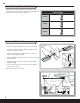
EN Control Surface Centering Tip: Use needle-nose pliers or ball link pliers (RVO1005) to remove or install a link on a control horn. IMPORTANT: Perform the Control Direction Test before performing control surface centering. • Turn the linkage clockwise or counterclockwise until the control surface is centered. Control Surface Centering and Adjusting a Linkage While AS3X® technology is inactive (before advancing the throttle), mechanically center the control surfaces.
EN SAFE™ Technology Flight Modes Panic Recovery Mode • If you feel you have lost control in any mode, hold the Panic Recovery button and reduce throttle. The SAFE technology will return the aircraft to upright flight. The included AR636 receiver has been programmed for operation in only this aircraft, providing the following selectable flight modes. The programming in this receiver cannot be changed by the user.
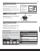
EN Center of Gravity (CG) The CG location is 82mm back from the leading edge of the wing at the root. For first flights, install the recommended flight battery all the way forward. Secure the battery with the strap as shown. Aircraft CG and weight is based on an E-flite 11.1V 2200mAh 30C battery (EFLB22003S30) installed. 82mm 3.23 inches back from the leading edge of the wing at the root.
EN AS3X Control Direction Test Rudder Aileron The AS3X system will not activate until the throttle stick or trim is increased for the first time after the flight battery is connected and the ESC switch is in the ON position. Once the AS3X is active, the control surfaces may move rapidly on the aircraft. This is normal. AS3X will remain active until the battery is disconnected or the ESC switch is in the OFF position.
EN Flying Tips Consult local laws and ordinances before choosing a flying location. Range Check your Radio System After final assembly, range check the radio system with the aircraft. Refer to your specific transmitter instruction manual. NOTICE: If a crash is imminent, reduce the throttle and trim fully. Failure to do so could result in extra damage to the airframe, as well as damage to the ESC and motor. NOTICE: Crash damage is not covered under warranty.
EN Guidlines for Flying 3D Getting Started This aircraft and its SAFE™ system were designed together to help an intermediate pilot apply standard flying skills to the demands of 3D flying. The calmer the wind conditions, the easier it is to execute maneuvers. Select the SAFE flight mode that supports the maneuver you want to perform. Hold the panic recovery button to help you escape difficulty in a maneuver.
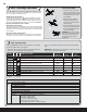
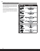
EN Motor Service Disassembly CAUTION: Always disconnect the flight battery from the aircraft before removing the propeller. 1. Remove the screw (A) and spinner (B) from the collet (C). 2. Remove the spinner nut (D), propeller (E), spinner backplate (F), backplate (G) and collet from the motor shaft (H). You will need a tool to turn the spinner nut. 3. Remove the 3 screws (I) from the cowling (J). Carefully remove the cowling from the fuselage. Paint may keep the cowling attached to the fuselage. 4.
EN Troubleshooting Guide Problem Aircraft will not respond to throttle but responds to other controls Extra propeller noise or extra vibration Possible Cause Throttle not at lowest position or throttle trim too high Throttle servo travel is lower than 100% Make sure throttle servo travel is 100% or greater Throttle channel is reversed Motor disconnected from ESC Damaged propeller and spinner, collet or motor Reverse throttle channel on transmitter Make sure motor is connected to the ESC Replace damaged
EN Limited Warranty What this Warranty Covers Horizon Hobby, LLC. (“Horizon”) warrants to the original purchaser that the product purchased (the “Product”) will be free from defects in materials and workmanship at the date of purchase.
EN FCC Infromation This device complies with part 15 of the FCC Rules. Operation is subject to the following two conditions: (1) This device may not cause harmful interference, and (2) this device must accept any interference received, including interference that may cause undesired operation. IC Infromation This device complies with Industry Canada licence-exempt RSS standard(s).
Replacement Parts • Ersatzteile • Pièces de rechange • Pezzi di ricambio Part # | Nummer Numéro | Codice Description Beschreibung Description PKZ8002 Decal Set: SU-29MM Dekorbogen: SU-29MM Planche de décalcomanies : SU-29MM Foglio con decalcomanie: SU-29MM PKZ8008 Spinner: SU-29MM Spinner: SU-29MM Cône : SU-29MM PKZ8006 Main gear set: SU-29MM Fahrwerksset: SU-29MM Jambes de train principal : SU-29MM Set ingranaggio principale: SU-29MM PKZ8021 Wing Tube: SU-29MM Flächenverbinder: SU-29MM
Optional Parts • Optionale Bauteile • Pièces optionnelles • Pezzi opzionali Part # | Nummer Numéro | Codice Description Beschreibung Description Descrizione EFLA250 Park Flyer Tool Assortment, 5 pc E-flite Park Flyer Werkzeugsortiment; 5 teilig Assortiment d'outils park flyer, 5pc Park Flyer assortimento attrezzi, 5 pc EFLAEC302 EC3 Battery Connector (2) E-flite EC3 Akkukabel, Buchse (2) Prises EC3 coté batterie (2) Connettore batteria EFLAEC303 ite EC3 Kabelsatz, Stecker/ EC3 Device/Battery Co
© 2014 Horizon Hobby, LLC. ParkZone, E-flite, Prophet, SAFE, the SAFE logo, AS3X, EC3, DSM, DSM2, DSMX, Z-Foam, the BNF logo, and ModelMatch are trademarks or registered trademarks of Horizon Hobby, LLC. The Spektrum trademark is used with permission of Bachmann Industries, Inc. JR is a registered trademark of JR Americas. Futaba is a registered trademark of Futaba Denshi Kogyo Kabushiki Kaisha Corporation of Japan. All other trademarks, service marks and logos are property of their respective owners. www.