
Brochure
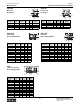
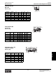


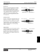
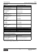
Table Of Contents
- MASTER TABLE of CONTENTS 1
- MASTER TABLE of CONTENTS 2ents 2
- CONTACT INFORMATION
- Cover
- Warning
- Your Preferred Supplier
- Value Added Services
- Value Added Parker Plus
- Residential AC Application
- Industrial Refrigeration Application
- Walk In Cooler Application
- Ice Machine Application
- Supermarket Application
- PHConnect
- EDI - Electronic Data Interchange
- Filter Dryer TOC
- Dryer Introduction
- Loose Filled Copper Dryers
- Loose Filled Spring Loaded Copper Dryers
- Service Copper Dryers
- Solid Core Copper Dryers
- Bi-Flow Copper Dryers
- Gold Label Steel Liquid Line Dryers
- Sahara Series Steel Liquid Line Dryers
- R410A Dryers
- BiFlow Stel Filter Dryers
- Gold Label Steel Suction Line Dryers
- Sahara Series Suction Line Dryers
- Dryer Shells and Cores
- Filter/Strainer/Oil Device TOC
- Accumulator, Receivers, Muffler TOC
- Sight Glass Moisture Indicator TOC
- Coupling TOC
- Service & Check Valve TOC
- TXV & AXV TOC
- Visual TOC 1
- Visual TOC 2
- S Series TXV
- I Series TXV
- EG Series TXV
- EGC Series TXV
- RE Series TXV
- H & HC Series TXV
- EC Series TXV
- ECC Series TXV
- G Series TXV
- N Series TXV
- C Series TXV
- B5 Series TXV
- PT Chart
- TXV Capacity Tables
- General TXV Information
- Valve Selection Procedure
- 104A & 104F Constant Pressure (AXV) Valves
- A Series Constant Pressure Valve (AXV)
- Model 139 Evaporator Pressure Regulator
- General Constant Pressure (AXV) Valve Information
- Model 625 Thermal Electric Valve
- Distributor & Flow Control TOC
- Refrigeration Solenoid Valves TOC
- R Series Refrigeration Solenoid Valves
- Introduction to Solenoid Valves
- Nomenclature
- General Specifications
- Ratings Summary
- R10 & R15 Series Solenoid Valves
- R20 & R25 Series Solenoid Valves
- R30 & R35 Solenoid Valves
- R40 & R45 Series Solenoid Valves
- R50 & R55 Series Solenoid Valves
- Electrical Specifications
- Coil Enclosures
- Capacity Tables
- Operating Principles
- Design Terminology
- Identification
- Agency Approvals
- Typical Applications
- 3-Way Hot Gas Defrost Valves
- Pulse Width Modulating Valves
- Secondary Coolant Solenoid Valves
- CROSS REFERENCE - R Series/Jackes Evans RB ORB
- Jackes Evans (RB/ORB Series)
- R Series Refrigeration Solenoid Valves
- General Purpose Solenoid Valves TOC
- FLO-CON Regulator & Valve TOC
- Overview
- (S)PORT & (S)PORT II Evaporator Pressure Regulators
- A8 Pressure Regulators
- A9 Pressure Regulators
- Suction Capacities A8, SPORT & SC
- A9 & A8 Condenser Bypass Capacities
- CK4 Check Valve
- Condenser Pressure Control
- Hot Gas Bypass
- Discharge Regulators for Supermarkets
- Crankcase Pressure Regulators
- SC Suction Solenoid Valves
- S81/S82 Solenoid Valves
- Abbreviations/Terminology
- Industrial Refrigeration TOC
- Warning/How to Use
- Pressure Regulators
- A2 Compact Regulators
- A2CK Relief Regulators
- A4 Adaptomode Regulators
- Weld End Regulators
- A2D Modular Presure Pilot
- S6A Modular Solenoid Pilot
- S6B Compact Modular Solenoid Pilot
- Modudapter
- Moduplate
- Vacuum Cartridge
- Outlet Regulator Kit
- Pressure Bonnet Kit
- Temperature Bonnet Kit
- Motor Bonnet Kit
- Electric Proportioning Thermostat
- Well, Separable
- Defrost Timer
- Handwheel
- Flange Ring-Tube Kits
- Class B Coil - S6A
- Class H Coil - S6B
- Voltages
- Solenoid Valves
- Gas Powered Suction Stop Valves
- Check Valves
- Safety Relief Valves
- Hand Valves
- Liquid Flow Regulators
- Refrigerant Float Switch
- Rapid Purger
- Automatic Liquid Drainer (ALD)
- Programmable Liquid Level Controller (PLLC)
- Flanges
- RS Strainers
- Liquid Drain Ball Valves
- Unibody Gauge Valves
- Gauges
- Depth Tracker Transducer Probes
- Open Refrigerant Pumps
- Hermetic Refrigerant Pumps
- Paint
- Warranties/Safe Operation
- Pressure in PSIG
- Pressure in Bar
- Offer of Sale
- Parker Hannifin Corporation
- Back Cover -CONTACT INFORMATION

Catalog CIC-2003-1/US
Couplings
Parker Hannifin Corporation
Climate & Industrial Controls Group
Cleveland, OH
83
Couplings
Assembly Instructions
After tubing or hose has been connected to
adapters (1) and (12), install adapter O-rings (2) and (11)*
on adapters. Be sure O-rings are not twisted.
Generously lubricate adapter O-rings (2) and (11)
with the system lubricant to prevent them from scuffing and
tearing when coupling body is threaded on adapter.
Adapter to S2 male coupling half connection.
A. Lubricate poppet face with system lubricant. Insert
poppet valve assembly (3) into body (4). Tighten
body (4) on adapter (1).
B. After body and adapter make metal-to-metal contact,
tighten by rotating body (4) 1/8" with respect to
adapter (1) or torque to the value shown in the
“Torque Values” table.
Adapter to S5 female coupling half connection.
A. Lubricate O-ring (9) liberally with system lubricant.
Insert valve and sleeve assembly (10) into body (8).
Tighten body (8) on adapter (12).
B. After body and adapter make metal-to-metal contact,
tighten by rotating body (8) 1/8" with respect to
adapter (12) or torque to the value shown in the
“Torque Values” table.
Coupling connection.
A. Generously lubricate the gasket seal (5) on the
5400-S2 male coupling half with the system lubricant.
B. Thread the union nut (8) onto the S2 male coupling
half. Tighten union nut to torque values shown in the
“Torque Values” table.
IMPORTANT - DO NOT rotate the S5 female
coupling half body during connection.
C. After the coupling halves are seated, keep the
bodies of the S2 male coupling half (4) and that of
the S5 female coupling half (8) from rotating and
tighten the union nut to the torque values shown in
the “Torque Values” table.
IMPORTANT - DO NOT rotate the S2 or S5 coupling
half body during connection.
Bulkhead Mounting — S2 Half
Install lock washer (6) on S2 half, insert S2 male
coupling half through bulkhead, and tighten jam-nut (7) so
that lock-washer teeth are fully compressed.
Note: Lock washer (6) must be between hex of S2
male half and bulkhead.
*IMPORTANT: Generous lubrication is required for all gaskets and O-rings. Lubrication should match system oil and be compatible
with refrigerant system
Assembly Instructions and Accessories
Dust Cap and Dust Plug
Dust
Cap
Dust
Plug
Adapter SAE 37° (JIC)
Adapter — Braze
O-Ring Required
O-Ring Required
Accessories
5400 Series Self-Sealing Steel Couplings
Step 1
Step 2
Step 3
Step 4
Step 5
Step 1
Coupling
Size
Dust Cap
with Gasket
Dust Plug
with Gasket
-4 5400-S6-4 5400-S8-4
-8 5400-S6-8 5400-S8-8
-12 5400-S6-12 5400-S8-12
-16 5400-S6-16 5400-S8-16
Part Numbers
Coupling
Thread
Size
Tube
O.D.
Size O-Ring Brass P Size
-4 22546-12 202208-4-4B 1/2-20 1/4
-8 22546-17 202208-8-8B 7/8-20 1/8
-12 22546-23 202208-10-12B 1-1/4 - 18 5/8
-16 22546-28 202208-14-16B 1-9/32 - 20 5/8
Part Numbers
Coupling
Thread
Size
Tube
O.D.
Size O-Ring Brass Steel P Size
-4 22546-12 202220-4-4B 202220-4-4S 7/16 - 20 1/4
-4 22546-12 202220-6-4B 202220-6-4S 9/16 - 18 3/8
-8 22546-17 202220-6-8B 202220-6-8S 9/16 - 18 3/8
-8 22546-17 202220-8-8B 202220-8-8S 3/4 -16 1/2
-12 22546-23 202220-10-12B 202220-10-12S 7/8 - 14 5/8
-12 22546-23 202220-10-12B 202220-10-12S 1-1/16 - 12 3/4
-16 22546-28 202220-16-16B 202220-16-16S 1-3/16 - 12 1
Part Numbers