
Brochure

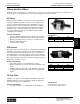
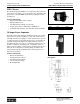

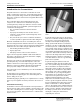
Table Of Contents
- MASTER TABLE of CONTENTS 1
- MASTER TABLE of CONTENTS 2ents 2
- CONTACT INFORMATION
- Cover
- Warning
- Your Preferred Supplier
- Value Added Services
- Value Added Parker Plus
- Residential AC Application
- Industrial Refrigeration Application
- Walk In Cooler Application
- Ice Machine Application
- Supermarket Application
- PHConnect
- EDI - Electronic Data Interchange
- Filter Dryer TOC
- Dryer Introduction
- Loose Filled Copper Dryers
- Loose Filled Spring Loaded Copper Dryers
- Service Copper Dryers
- Solid Core Copper Dryers
- Bi-Flow Copper Dryers
- Gold Label Steel Liquid Line Dryers
- Sahara Series Steel Liquid Line Dryers
- R410A Dryers
- BiFlow Stel Filter Dryers
- Gold Label Steel Suction Line Dryers
- Sahara Series Suction Line Dryers
- Dryer Shells and Cores
- Filter/Strainer/Oil Device TOC
- Accumulator, Receivers, Muffler TOC
- Sight Glass Moisture Indicator TOC
- Coupling TOC
- Service & Check Valve TOC
- TXV & AXV TOC
- Visual TOC 1
- Visual TOC 2
- S Series TXV
- I Series TXV
- EG Series TXV
- EGC Series TXV
- RE Series TXV
- H & HC Series TXV
- EC Series TXV
- ECC Series TXV
- G Series TXV
- N Series TXV
- C Series TXV
- B5 Series TXV
- PT Chart
- TXV Capacity Tables
- General TXV Information
- Valve Selection Procedure
- 104A & 104F Constant Pressure (AXV) Valves
- A Series Constant Pressure Valve (AXV)
- Model 139 Evaporator Pressure Regulator
- General Constant Pressure (AXV) Valve Information
- Model 625 Thermal Electric Valve
- Distributor & Flow Control TOC
- Refrigeration Solenoid Valves TOC
- R Series Refrigeration Solenoid Valves
- Introduction to Solenoid Valves
- Nomenclature
- General Specifications
- Ratings Summary
- R10 & R15 Series Solenoid Valves
- R20 & R25 Series Solenoid Valves
- R30 & R35 Solenoid Valves
- R40 & R45 Series Solenoid Valves
- R50 & R55 Series Solenoid Valves
- Electrical Specifications
- Coil Enclosures
- Capacity Tables
- Operating Principles
- Design Terminology
- Identification
- Agency Approvals
- Typical Applications
- 3-Way Hot Gas Defrost Valves
- Pulse Width Modulating Valves
- Secondary Coolant Solenoid Valves
- CROSS REFERENCE - R Series/Jackes Evans RB ORB
- Jackes Evans (RB/ORB Series)
- R Series Refrigeration Solenoid Valves
- General Purpose Solenoid Valves TOC
- FLO-CON Regulator & Valve TOC
- Overview
- (S)PORT & (S)PORT II Evaporator Pressure Regulators
- A8 Pressure Regulators
- A9 Pressure Regulators
- Suction Capacities A8, SPORT & SC
- A9 & A8 Condenser Bypass Capacities
- CK4 Check Valve
- Condenser Pressure Control
- Hot Gas Bypass
- Discharge Regulators for Supermarkets
- Crankcase Pressure Regulators
- SC Suction Solenoid Valves
- S81/S82 Solenoid Valves
- Abbreviations/Terminology
- Industrial Refrigeration TOC
- Warning/How to Use
- Pressure Regulators
- A2 Compact Regulators
- A2CK Relief Regulators
- A4 Adaptomode Regulators
- Weld End Regulators
- A2D Modular Presure Pilot
- S6A Modular Solenoid Pilot
- S6B Compact Modular Solenoid Pilot
- Modudapter
- Moduplate
- Vacuum Cartridge
- Outlet Regulator Kit
- Pressure Bonnet Kit
- Temperature Bonnet Kit
- Motor Bonnet Kit
- Electric Proportioning Thermostat
- Well, Separable
- Defrost Timer
- Handwheel
- Flange Ring-Tube Kits
- Class B Coil - S6A
- Class H Coil - S6B
- Voltages
- Solenoid Valves
- Gas Powered Suction Stop Valves
- Check Valves
- Safety Relief Valves
- Hand Valves
- Liquid Flow Regulators
- Refrigerant Float Switch
- Rapid Purger
- Automatic Liquid Drainer (ALD)
- Programmable Liquid Level Controller (PLLC)
- Flanges
- RS Strainers
- Liquid Drain Ball Valves
- Unibody Gauge Valves
- Gauges
- Depth Tracker Transducer Probes
- Open Refrigerant Pumps
- Hermetic Refrigerant Pumps
- Paint
- Warranties/Safe Operation
- Pressure in PSIG
- Pressure in Bar
- Offer of Sale
- Parker Hannifin Corporation
- Back Cover -CONTACT INFORMATION

Catalog CIC-2003-1/US
Accumulators, Receivers, Tanks and Mufflers
Parker Hannifin Corporation
Climate & Industrial Controls Group
Cleveland, OH
59
Accum'tors,
Receivers, Tanks
& Mufflers
The prime function of a suction line accumulator in a heat
pump or refrigeration system is to catch and hold any unused
portion of the system charge. It must also prevent liquid slug-
ging of the compressor and excessive refrigerant dilution of the
compressor oil.
The accumulator must return refrigerant and oil to the
compressor at a sufficient rate to maintain both system
operating efficiency and proper crankcase oil level. To make
sure these tasks are accomplished, system designers must
consider the following items:
• The accumulator must have sufficient internal
volume.
• A properly sized and protected oil return orifice is
required to ensure positive oil (and refrigerant) return
to the compressor.
• The pressure drop across the accumulator should be
as low as possible for given inlet and outlet fitting sizes.
Oil return at minimum flow rate is controlled by the outlet U-
tube size. Refrigerant and oil will be returned to the compressor
by pressure drop across the orifice metering area and the liquid
head above the orifice. Other design requirements include:
• Safe working and burst pressures.
• Agency approvals.
• Salt spray, moisture, and corrosion resistance.
Figure 1
shows a typical accumulator with an inlet deflector.
The shape of the deflector directs the inlet flow in a slightly
downward tangential direction.
The inlet to the U tube is located behind the inlet deflector to
prevent liquid carry-over and is bell-shaped to reduce the
sudden contraction loss of the high-velocity gas. The U-tube
diameter is selected to minimize pressure drop at high flow
rates yet provide adequate oil return at low flow rates.
A 50 x 60 mesh screen is installed to protect the small diameter
oil return orifice.
An anti-siphon hole, provided near the outlet of the U tube,
prevents liquid from siphoning into the outlet tubing and com-
pressor during an off cycle.
A fusible alloy plug is generally a U.L. requirement. It is a safety
device to protect against excessive pressures in the event of a
fire.
Accumulator Fine Tuning
Accumulator selection can be fine tuned for best performance.
This involves the sizing of the accumulator, and the sizing of the
orifice. The controlling factor for both is the type of metering de-
vice used on the system, either a fixed orifice or a thermostatic
expansion valve.
In systems using a fixed orifice in the heating
mode, the accumulator holding capacity should
be about 70% of the system charge. This
should provide adequate holding capacity
during operation with blocked or fouled heat
exchanger coils. The resulting high discharge/
low suction pressure condition will push much
of the system charge into the accumulator. The
oil return orifice size should be small to prevent
excess liquid refrigerant being returned to the
compressor. This would excessively reduce the
compressor discharge temperature, lowering
heating performance. Parker recommends a
0.040 inch diameter orifice as a good starting
point for these systems.
In systems using an expansion valve, the
accumulator holding capacity should be about
50% of the system charge. At startup and after
defrost, the bulb of the expansion valve is
warm. This causes flooding of the evaporator
and brings the accumulator into play until the
valve regains control. The accumulator must
also deal with off cycle refrigerant migration.
At shut down, the accumulator is the coldest
component in the system. This results in
migration of liquid refrigerant to the lower
temperature accumulator. This type of system
needs to get the refrigerant returned to circula-
tion more quickly than the fixed orifice system.
Parker recommends a 0.055 inch diameter
orifice to allow quick return of liquid refrigerant.
The recommended sizes of the orifices can be
further tested for optimum results. Parker has
the ability to provide orifices in sizes smaller
and larger to satisfy the characteristics
required by the customer.
Figure 1 - Typical accumulator with inlet deflector
baffle.
Introduction to Accumulators
Introduction to Accumulators Accumulators