
Brochure
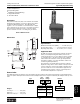
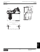
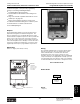
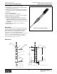
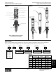

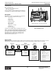
Table Of Contents
- MASTER TABLE of CONTENTS 1
- MASTER TABLE of CONTENTS 2ents 2
- CONTACT INFORMATION
- Cover
- Warning
- Your Preferred Supplier
- Value Added Services
- Value Added Parker Plus
- Residential AC Application
- Industrial Refrigeration Application
- Walk In Cooler Application
- Ice Machine Application
- Supermarket Application
- PHConnect
- EDI - Electronic Data Interchange
- Filter Dryer TOC
- Dryer Introduction
- Loose Filled Copper Dryers
- Loose Filled Spring Loaded Copper Dryers
- Service Copper Dryers
- Solid Core Copper Dryers
- Bi-Flow Copper Dryers
- Gold Label Steel Liquid Line Dryers
- Sahara Series Steel Liquid Line Dryers
- R410A Dryers
- BiFlow Stel Filter Dryers
- Gold Label Steel Suction Line Dryers
- Sahara Series Suction Line Dryers
- Dryer Shells and Cores
- Filter/Strainer/Oil Device TOC
- Accumulator, Receivers, Muffler TOC
- Sight Glass Moisture Indicator TOC
- Coupling TOC
- Service & Check Valve TOC
- TXV & AXV TOC
- Visual TOC 1
- Visual TOC 2
- S Series TXV
- I Series TXV
- EG Series TXV
- EGC Series TXV
- RE Series TXV
- H & HC Series TXV
- EC Series TXV
- ECC Series TXV
- G Series TXV
- N Series TXV
- C Series TXV
- B5 Series TXV
- PT Chart
- TXV Capacity Tables
- General TXV Information
- Valve Selection Procedure
- 104A & 104F Constant Pressure (AXV) Valves
- A Series Constant Pressure Valve (AXV)
- Model 139 Evaporator Pressure Regulator
- General Constant Pressure (AXV) Valve Information
- Model 625 Thermal Electric Valve
- Distributor & Flow Control TOC
- Refrigeration Solenoid Valves TOC
- R Series Refrigeration Solenoid Valves
- Introduction to Solenoid Valves
- Nomenclature
- General Specifications
- Ratings Summary
- R10 & R15 Series Solenoid Valves
- R20 & R25 Series Solenoid Valves
- R30 & R35 Solenoid Valves
- R40 & R45 Series Solenoid Valves
- R50 & R55 Series Solenoid Valves
- Electrical Specifications
- Coil Enclosures
- Capacity Tables
- Operating Principles
- Design Terminology
- Identification
- Agency Approvals
- Typical Applications
- 3-Way Hot Gas Defrost Valves
- Pulse Width Modulating Valves
- Secondary Coolant Solenoid Valves
- CROSS REFERENCE - R Series/Jackes Evans RB ORB
- Jackes Evans (RB/ORB Series)
- R Series Refrigeration Solenoid Valves
- General Purpose Solenoid Valves TOC
- FLO-CON Regulator & Valve TOC
- Overview
- (S)PORT & (S)PORT II Evaporator Pressure Regulators
- A8 Pressure Regulators
- A9 Pressure Regulators
- Suction Capacities A8, SPORT & SC
- A9 & A8 Condenser Bypass Capacities
- CK4 Check Valve
- Condenser Pressure Control
- Hot Gas Bypass
- Discharge Regulators for Supermarkets
- Crankcase Pressure Regulators
- SC Suction Solenoid Valves
- S81/S82 Solenoid Valves
- Abbreviations/Terminology
- Industrial Refrigeration TOC
- Warning/How to Use
- Pressure Regulators
- A2 Compact Regulators
- A2CK Relief Regulators
- A4 Adaptomode Regulators
- Weld End Regulators
- A2D Modular Presure Pilot
- S6A Modular Solenoid Pilot
- S6B Compact Modular Solenoid Pilot
- Modudapter
- Moduplate
- Vacuum Cartridge
- Outlet Regulator Kit
- Pressure Bonnet Kit
- Temperature Bonnet Kit
- Motor Bonnet Kit
- Electric Proportioning Thermostat
- Well, Separable
- Defrost Timer
- Handwheel
- Flange Ring-Tube Kits
- Class B Coil - S6A
- Class H Coil - S6B
- Voltages
- Solenoid Valves
- Gas Powered Suction Stop Valves
- Check Valves
- Safety Relief Valves
- Hand Valves
- Liquid Flow Regulators
- Refrigerant Float Switch
- Rapid Purger
- Automatic Liquid Drainer (ALD)
- Programmable Liquid Level Controller (PLLC)
- Flanges
- RS Strainers
- Liquid Drain Ball Valves
- Unibody Gauge Valves
- Gauges
- Depth Tracker Transducer Probes
- Open Refrigerant Pumps
- Hermetic Refrigerant Pumps
- Paint
- Warranties/Safe Operation
- Pressure in PSIG
- Pressure in Bar
- Offer of Sale
- Parker Hannifin Corporation
- Back Cover -CONTACT INFORMATION

Catalog CIC-2003-1/US
Industrial Refrigeration Products: Liquid Flow Regulators
Parker Hannifin Corporation
Climate & Industrial Controls Group
Cleveland, OH
421
Industrial
Refrigeration
Products
How to Order
Type AFR automatic flow regulators can be specified by using the symbols in the chart below to develop a model number. Select
only those symbols that represent the features desired, and place them in the sequence indicated by the example at the top of the
chart.
Type AFR (Adjustable Flow)
●
External Adjustment
●
Easy Setting Scale
●
Eliminates System Balancing
●
Integral Check Valve
●
“Frost Free” Neck
Description
This precision built, heavy duty, self-contained, iron bodied
Automatic Flow Regulator is used as a liquid control device
for Ammonia Overfeed Systems. This adjustable flow
regulator, once set, maintains a constant flow rate of liquid
to the evaporator; it also serves as a check valve to prevent
back flow into the liquid line from the evaporator during
pressure reversals such as occur during hot gas defrost.
Refer to Bulletin 41-10.
Dimensions
Application Note
An AFR flow regulator is designed to maintain an approxi-
mately constant liquid refrigerant delivery rate into the
evaporator. However, it is not an expansion device capable
of controlling vapor or two-phase flow. Design conditions,
which allow for the formation of flash gas as liquid flows
through the regulator, can cause the AFR to chatter and
result in irregular liquid delivery.
This feed device should be applied only where sufficient
liquid subcooling exists to ensure that its outlet pressure will
never be reduced to less than the liquid’s saturation vapor
pressure. AFR’s are not recommended for application in
gas displacement systems or where controlled pressure
receivers deliver liquid to the evaporators.
Specifications
Maximum Rated Pressure (MRP) ......... 27.6 bar (400 psi)
Pressure drop range ............... 0.35 to 3.5 bar (5 to 50 psi)
Operating temperature ........- 40° to 38° C (- 40° to 100° F)
32mm
(1.25")
104mm
(4.1")
317mm
(12.47")
Max.
186mm (7.31")
3/8, 1/2 or 3/4 FPT or SW
218mm (8.56")
3/8, 1/2 or 3/4 WN
79mm
(3.12")
Weights
Less flanges ....................... 3.6 kg (8 lb)
With flanges ....................... 4.1 kg (9 lb)
With strainer & flanges....... 5.0 kg (11 lb)
Flange Type Connection
X Less Flanges 00 None
F FPT (IPS) 03
3
/8"
S SW (IPS) 04 ½"
W Weld Neck (IPS) 06 ¾"
D DIN Weld Neck 10 10mm
15 15mm
20 20mm
Strainer
N No Strainer
S w/Strainer
AFR F04 F04 S
Inlet Outlet
Type Flange Flange Strainer
Technical Information, Dimensions and How to Order