
Brochure
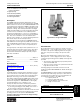
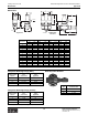

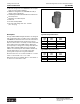
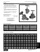
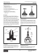
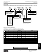


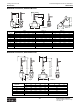
Table Of Contents
- MASTER TABLE of CONTENTS 1
- MASTER TABLE of CONTENTS 2ents 2
- CONTACT INFORMATION
- Cover
- Warning
- Your Preferred Supplier
- Value Added Services
- Value Added Parker Plus
- Residential AC Application
- Industrial Refrigeration Application
- Walk In Cooler Application
- Ice Machine Application
- Supermarket Application
- PHConnect
- EDI - Electronic Data Interchange
- Filter Dryer TOC
- Dryer Introduction
- Loose Filled Copper Dryers
- Loose Filled Spring Loaded Copper Dryers
- Service Copper Dryers
- Solid Core Copper Dryers
- Bi-Flow Copper Dryers
- Gold Label Steel Liquid Line Dryers
- Sahara Series Steel Liquid Line Dryers
- R410A Dryers
- BiFlow Stel Filter Dryers
- Gold Label Steel Suction Line Dryers
- Sahara Series Suction Line Dryers
- Dryer Shells and Cores
- Filter/Strainer/Oil Device TOC
- Accumulator, Receivers, Muffler TOC
- Sight Glass Moisture Indicator TOC
- Coupling TOC
- Service & Check Valve TOC
- TXV & AXV TOC
- Visual TOC 1
- Visual TOC 2
- S Series TXV
- I Series TXV
- EG Series TXV
- EGC Series TXV
- RE Series TXV
- H & HC Series TXV
- EC Series TXV
- ECC Series TXV
- G Series TXV
- N Series TXV
- C Series TXV
- B5 Series TXV
- PT Chart
- TXV Capacity Tables
- General TXV Information
- Valve Selection Procedure
- 104A & 104F Constant Pressure (AXV) Valves
- A Series Constant Pressure Valve (AXV)
- Model 139 Evaporator Pressure Regulator
- General Constant Pressure (AXV) Valve Information
- Model 625 Thermal Electric Valve
- Distributor & Flow Control TOC
- Refrigeration Solenoid Valves TOC
- R Series Refrigeration Solenoid Valves
- Introduction to Solenoid Valves
- Nomenclature
- General Specifications
- Ratings Summary
- R10 & R15 Series Solenoid Valves
- R20 & R25 Series Solenoid Valves
- R30 & R35 Solenoid Valves
- R40 & R45 Series Solenoid Valves
- R50 & R55 Series Solenoid Valves
- Electrical Specifications
- Coil Enclosures
- Capacity Tables
- Operating Principles
- Design Terminology
- Identification
- Agency Approvals
- Typical Applications
- 3-Way Hot Gas Defrost Valves
- Pulse Width Modulating Valves
- Secondary Coolant Solenoid Valves
- CROSS REFERENCE - R Series/Jackes Evans RB ORB
- Jackes Evans (RB/ORB Series)
- R Series Refrigeration Solenoid Valves
- General Purpose Solenoid Valves TOC
- FLO-CON Regulator & Valve TOC
- Overview
- (S)PORT & (S)PORT II Evaporator Pressure Regulators
- A8 Pressure Regulators
- A9 Pressure Regulators
- Suction Capacities A8, SPORT & SC
- A9 & A8 Condenser Bypass Capacities
- CK4 Check Valve
- Condenser Pressure Control
- Hot Gas Bypass
- Discharge Regulators for Supermarkets
- Crankcase Pressure Regulators
- SC Suction Solenoid Valves
- S81/S82 Solenoid Valves
- Abbreviations/Terminology
- Industrial Refrigeration TOC
- Warning/How to Use
- Pressure Regulators
- A2 Compact Regulators
- A2CK Relief Regulators
- A4 Adaptomode Regulators
- Weld End Regulators
- A2D Modular Presure Pilot
- S6A Modular Solenoid Pilot
- S6B Compact Modular Solenoid Pilot
- Modudapter
- Moduplate
- Vacuum Cartridge
- Outlet Regulator Kit
- Pressure Bonnet Kit
- Temperature Bonnet Kit
- Motor Bonnet Kit
- Electric Proportioning Thermostat
- Well, Separable
- Defrost Timer
- Handwheel
- Flange Ring-Tube Kits
- Class B Coil - S6A
- Class H Coil - S6B
- Voltages
- Solenoid Valves
- Gas Powered Suction Stop Valves
- Check Valves
- Safety Relief Valves
- Hand Valves
- Liquid Flow Regulators
- Refrigerant Float Switch
- Rapid Purger
- Automatic Liquid Drainer (ALD)
- Programmable Liquid Level Controller (PLLC)
- Flanges
- RS Strainers
- Liquid Drain Ball Valves
- Unibody Gauge Valves
- Gauges
- Depth Tracker Transducer Probes
- Open Refrigerant Pumps
- Hermetic Refrigerant Pumps
- Paint
- Warranties/Safe Operation
- Pressure in PSIG
- Pressure in Bar
- Offer of Sale
- Parker Hannifin Corporation
- Back Cover -CONTACT INFORMATION

Catalog CIC-2003-1/US
Industrial Refrigeration Products: Safety Relief Valves
Parker Hannifin Corporation
Climate & Industrial Controls Group
Cleveland, OH
411
Industrial
Refrigeration
Products
Type H, M
●
For use with R-22, R-717 and other
common refrigerants
●
High Capacity
●
Excellent Repeatability
●
Unaffected by Vibration
●
Drain Plug Standard
Description
The Type H High Capacity Safety Relief Valves are de-
signed and constructed to meet the requirements of ASME
Boiler and Pressure Vessel Code and ANSI/ASHRAE 15-78
Code requirements and bear the ASME Code Symbol (UV)
indicating compliance with these codes. Employing proven
principles of design, these Safety Relief Valves are highly
reliable and dependable. Precision machined moving parts
of stainless steel, a PTFE disc and a cadmium-plated
spring prevent sticking due to corrosion or cold welding, to
assure valve opening at the set pressure long after installa-
tion. They are not suitable for corrosive ambient atmo-
spheres such as chlorine, etc. The two-bolt flanged bottom
inlet affords simple removal and replacement.
Two relief valves can be mounted on a Type M Dual Stop
Valve Manifold. This arrangement permits either valve to be
shut off individually and removed for repairs or inspection.
Thus, one valve is always in service as required by most
codes.
The high capacity of the Type H valve permits the use of a
small size valve which results in space saving. The valves
are very sturdy and compact, requiring small headroom.
The dual valve manifold assembly is especially compact
and easily assembled.
Materials
Body ..................................................................... Gray Iron
Internal Parts ..............................................Stainless Steel
Seat ........................................................................... PTFE
Specifications
Maximum Temperature ............................... 150° C (300°F)
See page 413 for capacities.
Application
Used with ammonia and halocarbon refrigerants in noncor-
rosive environments, Relief Valves protect each refrigera-
tion system pressure vessel that can be isolated by valves.
Municipal codes may govern selection and installation.
They may be patterned after the ASME boiler and pressure
vessel code and the ANSI/ASHRAE 15-78 safety code for
mechanical refrigeration. ANSI/ASHRAE 15-78 is highly
recommended if there is no compulsory code.
The Type H safety relief valve is intended to prevent the
pressure of the vessel from rising more than 10% above:
(1) the design working pressure (DWP) of the vessel or
(2) the pressure setting of the relief device.
Whenever conditions permit, it is advisable to have the relief
valve pressure setting at least 25% higher than the normal
operating pressure for the system.
The relief valve
pressure setting must not exceed the design working
pressure of the vessel.
Selection Data
On positive displacement compressor systems, pressure
limiting devices – such as high presure cutouts – must stop
the action of the pressure imposing element at no higher
than 90% of the pressure setting of the pressure relief
device.
On non-positive displacement compressors, pressure
limiting devices – such as high pressure cutout – may be
set at the design working pressure (DWP) of the high side,
provided:
1. The low side is protected bya properly sized pressure
at the low side DWP and
2. There are not stop valves in the system that isolate the
high side from the low side.
Discharge piping from relief devices must not exceed
lengths specified in ANSI/ASHRAE 15-78 with discharge to
atmosphere.
Per ANSI/ASHRAE 15-78, the formula for determining the
minimum required discharge capacity of a relief device for
each pressure vessel where the vessel is valved off from
the refrigerating systems is: C = FDL, where:
C = capacity, lb/min air
F = a factor from the table below
D = outside diameter of the vessel in feet
L = length of vessel in feet
Refrigerant Factor (F)
R-717 0.5
R-22 1.6
Consult factory for other refrigerants.
Type H Valves on Type M Manifold
Refer to Bulletin 70-01.
Technical Information