
Brochure
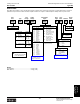

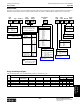
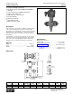
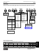
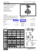
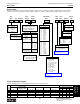
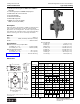
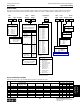
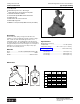
Table Of Contents
- MASTER TABLE of CONTENTS 1
- MASTER TABLE of CONTENTS 2ents 2
- CONTACT INFORMATION
- Cover
- Warning
- Your Preferred Supplier
- Value Added Services
- Value Added Parker Plus
- Residential AC Application
- Industrial Refrigeration Application
- Walk In Cooler Application
- Ice Machine Application
- Supermarket Application
- PHConnect
- EDI - Electronic Data Interchange
- Filter Dryer TOC
- Dryer Introduction
- Loose Filled Copper Dryers
- Loose Filled Spring Loaded Copper Dryers
- Service Copper Dryers
- Solid Core Copper Dryers
- Bi-Flow Copper Dryers
- Gold Label Steel Liquid Line Dryers
- Sahara Series Steel Liquid Line Dryers
- R410A Dryers
- BiFlow Stel Filter Dryers
- Gold Label Steel Suction Line Dryers
- Sahara Series Suction Line Dryers
- Dryer Shells and Cores
- Filter/Strainer/Oil Device TOC
- Accumulator, Receivers, Muffler TOC
- Sight Glass Moisture Indicator TOC
- Coupling TOC
- Service & Check Valve TOC
- TXV & AXV TOC
- Visual TOC 1
- Visual TOC 2
- S Series TXV
- I Series TXV
- EG Series TXV
- EGC Series TXV
- RE Series TXV
- H & HC Series TXV
- EC Series TXV
- ECC Series TXV
- G Series TXV
- N Series TXV
- C Series TXV
- B5 Series TXV
- PT Chart
- TXV Capacity Tables
- General TXV Information
- Valve Selection Procedure
- 104A & 104F Constant Pressure (AXV) Valves
- A Series Constant Pressure Valve (AXV)
- Model 139 Evaporator Pressure Regulator
- General Constant Pressure (AXV) Valve Information
- Model 625 Thermal Electric Valve
- Distributor & Flow Control TOC
- Refrigeration Solenoid Valves TOC
- R Series Refrigeration Solenoid Valves
- Introduction to Solenoid Valves
- Nomenclature
- General Specifications
- Ratings Summary
- R10 & R15 Series Solenoid Valves
- R20 & R25 Series Solenoid Valves
- R30 & R35 Solenoid Valves
- R40 & R45 Series Solenoid Valves
- R50 & R55 Series Solenoid Valves
- Electrical Specifications
- Coil Enclosures
- Capacity Tables
- Operating Principles
- Design Terminology
- Identification
- Agency Approvals
- Typical Applications
- 3-Way Hot Gas Defrost Valves
- Pulse Width Modulating Valves
- Secondary Coolant Solenoid Valves
- CROSS REFERENCE - R Series/Jackes Evans RB ORB
- Jackes Evans (RB/ORB Series)
- R Series Refrigeration Solenoid Valves
- General Purpose Solenoid Valves TOC
- FLO-CON Regulator & Valve TOC
- Overview
- (S)PORT & (S)PORT II Evaporator Pressure Regulators
- A8 Pressure Regulators
- A9 Pressure Regulators
- Suction Capacities A8, SPORT & SC
- A9 & A8 Condenser Bypass Capacities
- CK4 Check Valve
- Condenser Pressure Control
- Hot Gas Bypass
- Discharge Regulators for Supermarkets
- Crankcase Pressure Regulators
- SC Suction Solenoid Valves
- S81/S82 Solenoid Valves
- Abbreviations/Terminology
- Industrial Refrigeration TOC
- Warning/How to Use
- Pressure Regulators
- A2 Compact Regulators
- A2CK Relief Regulators
- A4 Adaptomode Regulators
- Weld End Regulators
- A2D Modular Presure Pilot
- S6A Modular Solenoid Pilot
- S6B Compact Modular Solenoid Pilot
- Modudapter
- Moduplate
- Vacuum Cartridge
- Outlet Regulator Kit
- Pressure Bonnet Kit
- Temperature Bonnet Kit
- Motor Bonnet Kit
- Electric Proportioning Thermostat
- Well, Separable
- Defrost Timer
- Handwheel
- Flange Ring-Tube Kits
- Class B Coil - S6A
- Class H Coil - S6B
- Voltages
- Solenoid Valves
- Gas Powered Suction Stop Valves
- Check Valves
- Safety Relief Valves
- Hand Valves
- Liquid Flow Regulators
- Refrigerant Float Switch
- Rapid Purger
- Automatic Liquid Drainer (ALD)
- Programmable Liquid Level Controller (PLLC)
- Flanges
- RS Strainers
- Liquid Drain Ball Valves
- Unibody Gauge Valves
- Gauges
- Depth Tracker Transducer Probes
- Open Refrigerant Pumps
- Hermetic Refrigerant Pumps
- Paint
- Warranties/Safe Operation
- Pressure in PSIG
- Pressure in Bar
- Offer of Sale
- Parker Hannifin Corporation
- Back Cover -CONTACT INFORMATION

Parker Hannifin Corporation
Climate & Industrial Controls Group
Cleveland, OH
Catalog CIC-2003-1/US
388
Industrial Refrigeration Products: Solenoid Valves
●
Standard Coil Housing Meets NEMA 3R and NEMA 4 –
Rain Tight
●
Coil Housing Surpasses NEMA Salt Spray Test
●
Molded Class “B” Coil Construction
●
Pilot Light Available
●
Stainless Steel Needle
●
Manual Opening Stem
●
MOPD is 20.7 bar (300 PSIG);
MRP is 27.6 bar (400 PSIG)
Description
This heavy duty solenoid valve is suitable for ammonia and
other common refrigerants, certain oils and other fluids
approved for use in refrigeration. The S4 is a pilot operated
valve that may be opened by means of the manual opening
stem for servicing or in case of electrical power failure.
Materials
Body ..................................................................... Gray Iron
Seat.........................PTFE (13-32mm), Metal (40-100mm)
Needle......................................................... Stainless Steel
Specifications
Minimum Pressure Drop to Open Wide
20-32mm (¾" - 1¼") ......................... 0.14 bar (2 PSI)
40-100mm (1
5
⁄8" - 4") ........................ 0.28 bar (4 PSI)
Minimum Fluid Temperature
20-32mm (¾" - 1¼") ............................. -45° C (-50° F)
40-100mm (1
5
⁄8" - 4") ............................ -50° C (-60°F)
Coil (See page 394).............................. Class “B” Housing
Type S4 (20-100mm)
PORT SIZE
20mm (3/4") 32mm 40 & 50mm 65mm 75mm 100mm
Dimension & 25mm (1") (1-1/4") (1-5/8" & 2") (2-1/2") (3") (4")
A mm 376 394 442 467 579 645
inch 14.8 15.5 17.4 18.4 22.8 25.4
B mm 148 162 177 181 273 292
inch 5.8 6.3 6.9 7.1 10.7 11.5
C mm 164 203 251 251 311 339
inch 6.2 8.0 9.9 9.9 12.2 14.1
D mm 216 256 307 331 389 450
(FPT,SW) inch 8.5 10.1 12.1 13.0 15.3 17.7
1¼ 1½ 1½ 2
E mm 261 300 304 364 371 401 478 571
(WN) inch 10.3 11.8 12.0 14.3 14.6 15.8 18.8 22.5
1
3
/8 1
5
/8 2
1
/8 1
5
/8 2
1
/8 2
5
/8 2
5
/8 3
1
/8 3
1
/8 3
5
/8
F mm 239 269 279 304 358 338 358 348 389 414 432 303
(ODS) inch 9.4 10.6 11.0 12.0 14.1 13.3 14.1 13.7 15.3 16.3 17.0 19.8
G mm 98 178 251 314 314 363
inch 3.9 7.0 9.9 12.4 12.4 14.3
H mm 117 117 140 159 176 222
inch 4.6 4.6 5.5 6.2 7.0 8.8
J mm 224 231 284 300 312 353
inch 8.8 9.1 11.2 11.8 12.3 13.9
1
3
/8 1
5
/8 2
1
/8 1
5
/8 2
1
/8 2
5
/8 2
5
/8 3
1
/8 3
1
/8 3
5
/8 4
1
/8
N mm 25 25283328333838434348 55
(ODS) inch 1.0 1.0 1.1 1.3 1.1 1.3 1.5 1.5 1.7 1.7 1.9 2.2
1-1/4 1-1/2 1-1/2 2
Pmm 13 15151515 25 29 32
(SW) inch 0.5 0.6 0.6 0.6 0.6 1.0 1.1 1.3
Flow Coefficients
20 mm (¾") ......................................... 6.2 Kv (7.2 Cv)
25 mm (1") ........................................ 8.6 Kv (10.0 Cv)
32mm (1¼") .................................... 15.0 Kv (17.5 Cv)
40 mm (1
5
⁄8") ................................... 28.6 Kv (33.4 Cv)
50 mm (2") ...................................... 42.4 Kv (49.5 Cv)
65 mm (2½") ................................... 59.9 Kv (70.0 Cv)
75 mm (3") ....................................... 86.0 Kv (100 Cv)
100 mm (4") ...................................... 139 Kv (162 Cv)
P
PIPE ENGAGEMENT
H
MAX.
J
B
A
C
D
G
(FPT FLANGES)
(SW FLANGES)
ADD FOR
STRAINER
N
F
BETWEEN
TUBE
STOPS
E
WELD NECK
FLANGES
O.D.S. SOLDER
FLANGES
Dimensions
Note: Allow 100mm (4") above valve for removal of coil
housing and coil.
Technical Information